Understanding complex system behaviors is a cornerstone of successful software engineering. When teams work together, clarity in process flow becomes just as important as the code itself. UML activity diagrams provide a visual representation of workflows, decisions, and actions within a system. They bridge the gap between abstract requirements and concrete implementation steps. This guide addresses the most frequent questions regarding the practical application of these diagrams in collaborative environments.
Whether you are a developer, analyst, or project manager, knowing how to model activity effectively ensures alignment across the board. This document covers definitions, practical usage, common misconceptions, and strategies for maintaining these diagrams throughout the software lifecycle.
📌 What Exactly Is an Activity Diagram?
An activity diagram is a behavioral diagram in the Unified Modeling Language (UML). It describes the dynamic aspects of a system. Unlike structural diagrams that show components, activity diagrams focus on the flow of control and data. They model the logic of a use case or a specific business process.
- Visual Logic: They show the sequence of steps from start to finish.
- Decision Points: They highlight where paths diverge based on conditions.
- Parallelism: They represent concurrent activities that happen simultaneously.
- State Transitions: They can indicate how an object changes state during a process.
Teams often confuse these with simple flowcharts. While similar, activity diagrams offer specific constructs for object flows, object nodes, and swimlanes that standard flowcharts lack. Swimlanes are particularly useful in team settings as they assign responsibility to specific roles or departments.
🔄 How Do Activity Diagrams Differ From Flowcharts?
This is a common point of confusion. Both visualize processes, but their scope and notation differ significantly. Understanding the distinction helps teams choose the right tool for the job.
| Feature | Flowchart | UML Activity Diagram |
|---|---|---|
| Scope | General business processes, algorithms | Software system behavior, object interactions |
| Concurrency | Difficult to represent clearly | Native support with fork and join nodes |
| Swimlanes | Supported but informal | Formal partitions for organizational structure |
| Object Flow | Not standard | Tracks data and objects between actions |
| Standard | Varies by tool or author | Strict UML specification |
For software engineering teams, the UML standard ensures that diagrams are readable by all stakeholders familiar with the notation. This reduces ambiguity during code reviews or architectural planning.
⚙️ Which Symbols Are Essential for Team Modeling?
To communicate effectively, every team member should recognize the core symbols. While there are many variations, a core set covers 90% of use cases. Memorizing these ensures smooth collaboration during diagramming sessions.
Core Symbols and Their Meanings
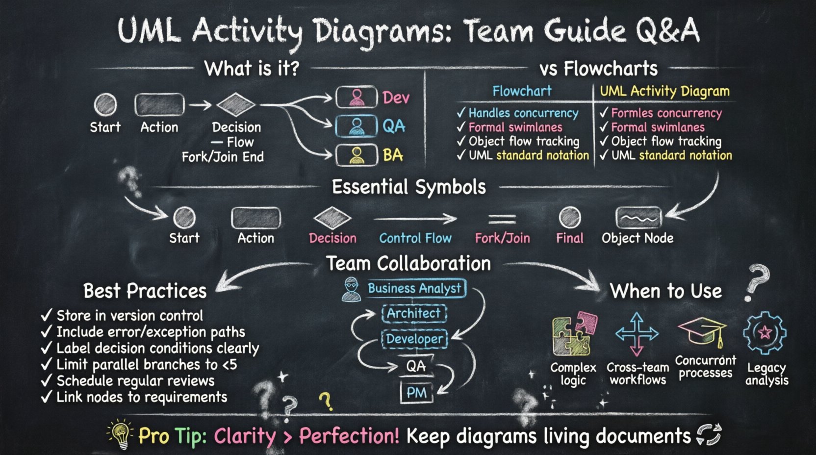
- Initial Node (Black Circle): Marks the starting point of the activity.
- Activity (Rounded Rectangle): Represents a specific action or function.
- Decision Node (Diamond): Indicates a branch based on a condition (e.g., Yes/No).
- Control Flow (Arrow): Shows the sequence of execution.
- Fork Node (Short Line): Splits a single flow into multiple concurrent flows.
- Join Node (Short Line): Merges multiple concurrent flows back into one.
- Final Node (Black Circle with Border): Marks the end of the process.
- Object Node (Rectangle): Represents data or objects existing at a specific point.
Using swimlanes is also critical. Each lane represents a distinct actor, system component, or team department. This visual separation prevents confusion about who is responsible for which action.
🧩 How Should Teams Handle Concurrency?
Real-world systems rarely run in a single straight line. Users might submit a form while a background process validates data. Activity diagrams excel at modeling this parallelism. However, managing concurrency visually can be tricky.
When designing concurrent paths, follow these guidelines:
- Use Fork Nodes: Place a fork where the flow splits. This indicates that all outgoing paths begin simultaneously.
- Use Join Nodes: Place a join where the paths merge. The process continues only after all incoming paths complete.
- Avoid Deadlocks: Ensure that join nodes do not wait for paths that will never arrive. Verify that every fork has a corresponding join.
- Label Conditions: Clearly label decision nodes with the specific logic governing the path (e.g., “Payment Approved”).
- Limit Fan-Out: Avoid splitting into too many parallel paths. If you see five or more, consider breaking the diagram into sub-activities.
Concurrency is often the source of race conditions in code. Visualizing this flow early helps developers anticipate threading issues or asynchronous data handling requirements.
👥 Who Should Participate in Diagram Creation?
Creating an activity diagram is a collaborative effort. It is not solely the responsibility of one person. Different perspectives ensure the diagram reflects reality rather than an idealized process.
- Business Analysts: Define the business rules and high-level workflows. They ensure the diagram matches stakeholder expectations.
- System Architects: Ensure technical feasibility. They identify where components interact and where data flows.
- Developers: Provide input on implementation complexity. They clarify edge cases that might not be obvious at a high level.
- QA Engineers: Identify testable scenarios. They help define the decision paths that require validation.
- Project Managers: Track dependencies. They use the diagram to estimate timelines and resource allocation.
Involving this group creates a shared understanding. When the diagram is finished, everyone has signed off on the logic. This reduces the likelihood of rework during the implementation phase.
🛠️ How Do You Maintain Diagrams Over Time?
One of the biggest challenges with documentation is keeping it current. Software evolves, and processes change. An outdated diagram is worse than no diagram at all, as it misleads the team.
To maintain accuracy:
- Version Control: Store diagrams in the same repository as the code. Use version history to track changes.
- Link to Requirements: Connect diagram nodes to specific requirement IDs. This makes it easy to see if a requirement has been dropped.
- Review Cycles: Schedule regular reviews. Update diagrams during sprint planning or architectural review meetings.
- Automate Where Possible: If your tooling allows, generate diagrams from code snippets or models. This reduces manual entry errors.
- Designate Owners: Assign a specific role to maintain the diagram. If everyone owns it, often no one does.
Treat the diagram as a living artifact. It should evolve alongside the software. If a process changes, the diagram must be updated before the code is deployed.
❌ What Are Common Pitfalls to Avoid?
Even experienced teams make mistakes when modeling activities. Recognizing these traps helps maintain the quality of the documentation.
- Too Much Detail: Do not try to capture every single line of code. Activity diagrams are for logic, not implementation specifics. Keep the granularity appropriate for the audience.
- Ignoring Error Handling: Many diagrams only show the “happy path.” You must include branches for failures, timeouts, and exceptions.
- Overlapping Swimlanes: Avoid assigning a single activity to multiple lanes. This creates ambiguity about ownership.
- Disconnected Flows: Ensure every node is reachable. Dead ends confuse the reader and suggest incomplete logic.
- Ignoring Data: Don’t just show actions; show what data is consumed and produced. Object flows add context to the control flow.
- Inconsistent Notation: Use the same shapes for the same types of actions throughout the entire document. Consistency aids readability.
🔗 How Do Activity Diagrams Integrate With Other Models?
Activity diagrams do not exist in isolation. They are part of a larger ecosystem of UML diagrams. Integrating them with other views provides a complete picture of the system.
Use Case Diagrams
Use case diagrams identify who does what. Activity diagrams explain how the action is performed. A single use case can have multiple activity diagrams representing different flows (e.g., normal flow, alternate flow).
Sequence Diagrams
Sequence diagrams focus on object interactions over time. Activity diagrams focus on the logic flow. Use activity diagrams to define the high-level logic, then use sequence diagrams to detail the message passing between objects for complex actions.
State Machine Diagrams
State diagrams show the lifecycle of a single object. Activity diagrams show the flow of a process. If a process involves complex state changes of a specific entity, consider using a state diagram for that entity within the activity flow.
Class Diagrams
Class diagrams define the static structure. Activity diagrams define the dynamic behavior. Ensure that the objects mentioned in the activity diagram exist in the class diagram. This validates that the logic is supported by the structure.
📊 When Is It Necessary to Create One?
Not every project requires an activity diagram. Over-modeling leads to wasted effort. Determine if the complexity warrants the investment.
- Complex Business Logic: If the process involves multiple decision points and conditions, a diagram clarifies the rules.
- Multi-Department Processes: If data passes between different teams, swimlanes clarify handoffs.
- Parallel Processing: If background tasks, user actions, and system updates happen simultaneously, visualization is required.
- New Team Onboarding: Use diagrams to train new members on existing workflows quickly.
- Legacy System Analysis: Use diagrams to reverse-engineer undocumented processes.
For simple scripts or linear tasks, a text description or code comments may suffice. Reserve diagrams for scenarios where visual complexity aids understanding.
🧠 How Do You Ensure Team Alignment?
The goal of the diagram is communication. If the team does not agree on the visual representation, the diagram fails its purpose.
- Workshop Sessions: Draw the diagram together on a whiteboard or digital canvas. Real-time collaboration catches errors immediately.
- Peer Reviews: Have a team member who was not involved in the creation review the diagram. Fresh eyes spot logic gaps.
- Define Standards: Agree on a notation standard at the start of the project. Do not mix styles.
- Accessible Tools: Ensure the tool used is accessible to all team members. If only one person can edit it, collaboration suffers.
- Feedback Loops: Encourage feedback during the design phase. Do not treat the diagram as final until implementation begins.
Alignment is not a one-time event. It requires continuous communication. Regular check-ins ensure the diagram remains a source of truth.
🛡️ What Security Considerations Apply?
Activity diagrams often reveal sensitive business logic. While they are technical documents, they can expose vulnerabilities or proprietary processes.
- Access Control: Restrict access to detailed diagrams if they reveal security-critical paths.
- Sanitization: Avoid including real data values in examples. Use placeholders like “User ID” instead of “12345”.
- Compliance: Ensure the modeling process adheres to data privacy regulations. Do not diagram PII (Personally Identifiable Information) flows without care.
🚀 Final Thoughts on Workflow Modeling
UML activity diagrams are powerful tools for clarifying system behavior. They transform abstract requirements into concrete visual logic. When used correctly, they reduce misunderstandings and streamline development.
Success depends on discipline. Teams must commit to maintaining the diagrams as the system evolves. They must involve the right stakeholders and avoid unnecessary complexity. By following these guidelines, teams can leverage activity diagrams to build more robust, understandable, and maintainable software systems.
Remember that the diagram is a means to an end. The goal is better software, not perfect drawings. Focus on clarity, accuracy, and communication above all else. With practice, your team will find that these diagrams become an indispensable part of your development workflow.