
Building an Online Order Process Context Diagram with VPasCode
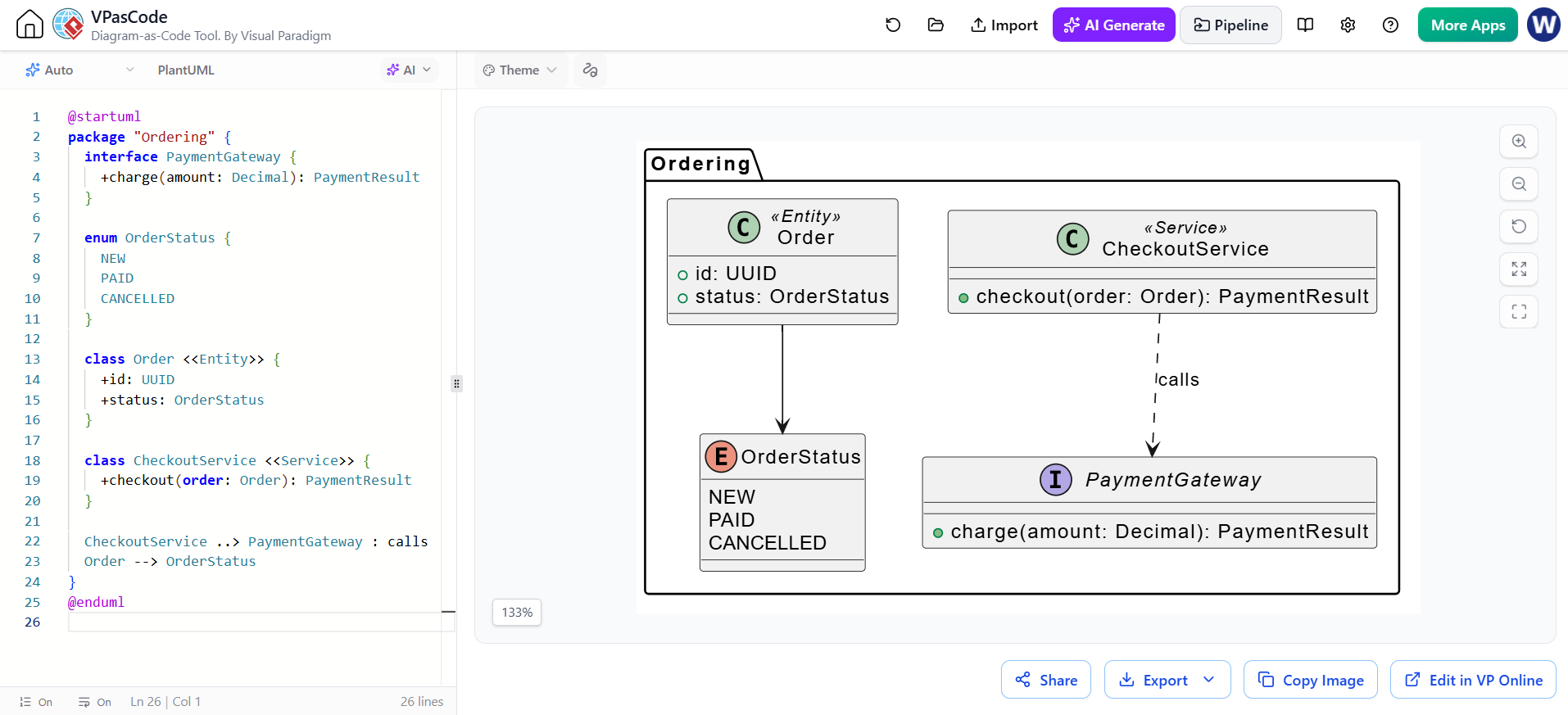
In the world of software architecture, defining the boundaries of your system and the specific contracts between its components is critical. Using a “Diagram-as-Code” approach allows you to version control your architecture alongside your source code. This tutorial explores a specific scenario using VPasCode to model an Ordering System context, demonstrating how to utilize PlantUML to define interfaces, enumerations, packages, and stereotypes effectively.
1. The Power of Packages: Grouping Context
The foundation of this diagram is the package directive. In complex systems, you rarely have a flat list of classes. You need logical grouping. Here, the package "Ordering" creates a visual boundary that encapsulates the specific business domain of managing orders. This prevents naming conflicts and visually groups related types, making the system’s scope immediately clear to stakeholders.
2. Interfaces vs. Implementation
The diagram introduces the concept of the interface. Notice the PaymentGateway. An interface in this context represents a contract—a promise of behavior—without dictating how that behavior is implemented. By defining +charge(amount: Decimal): PaymentResult, we establish a strict API. This allows the rest of the system to interact with payment providers without knowing if the underlying provider is Stripe, PayPal, or a custom solution.
3. Enumerations: Managing State
Data integrity is maintained through enum declarations. The OrderStatus enumeration restricts the possible states of an order to a finite set: NEW, PAID, and CANCELLED. In the generated diagram, this is rendered as a distinct class-like structure containing these fixed values, ensuring that the Order class only references valid states.
4. Stereotypes: Semantic Context
One of the most powerful features in this modeling example is the use of Stereotypes. In PlantUML, these are defined using double angle brackets, such as class Order <<Entity>>. This is not just decorative; it provides semantic context. It tells the reader that the Order class represents core business data (an Entity), while CheckoutService represents logic (a Service). This distinction is vital for understanding the Single Responsibility Principle within your architecture.
5. Modeling Relationships
Finally, we define how these components interact. The diagram uses two distinct types of relationships:
- Dependency (Dashed Arrow):
CheckoutService ..> PaymentGateway : calls. This indicates that the Service layer relies on the Interface to perform its work. - Association (Solid Arrow):
Order --> OrderStatus. This indicates that the Order class holds a reference to the OrderStatus enum.
Complete Code Example
The following code snippet, used in VPasCode, generates the architecture diagram. It serves as a reference for structuring your own PlantUML files.
@startuml
package "Ordering" {
  interface PaymentGateway {
    +charge(amount: Decimal): PaymentResult
  }

  enum OrderStatus {
    NEW
    PAID
    CANCELLED
  }

  class Order <<Entity>> {
    +id: UUID
    +status: OrderStatus
  }

  class CheckoutService <<Service>> {
    +checkout(order: Order): PaymentResult
  }

  CheckoutService ..> PaymentGateway : calls
  Order --> OrderStatus
}
@endumlConclusion
By combining standard UML syntax with specific VPasCode/PlantUML capabilities like stereotypes, you can create diagrams that are not only visually appealing but also semantically rich. This approach ensures that your documentation remains a single source of truth, tightly coupled with your codebase.