


When the gap between a design model and actual system execution widens, engineering teams face critical challenges. This is particularly true for UML Timing Diagrams, which serve as the blueprint for time-critical interactions. These diagrams map out how objects behave over time, specifying exact constraints on message arrival and state changes. However, discrepancies often arise during implementation. The code behaves differently than the model predicts. This divergence can lead to race conditions, missed deadlines, and system instability. Understanding how to troubleshoot these mismatches is essential for maintaining system integrity.
This guide explores the mechanics of identifying and resolving timing anomalies. We will examine the structural elements of timing models, common causes for behavioral drift, and systematic methods for validation. By aligning your timing constraints with reality, you ensure that the system performs reliably under load. Let us begin by defining the core components and where errors typically originate.
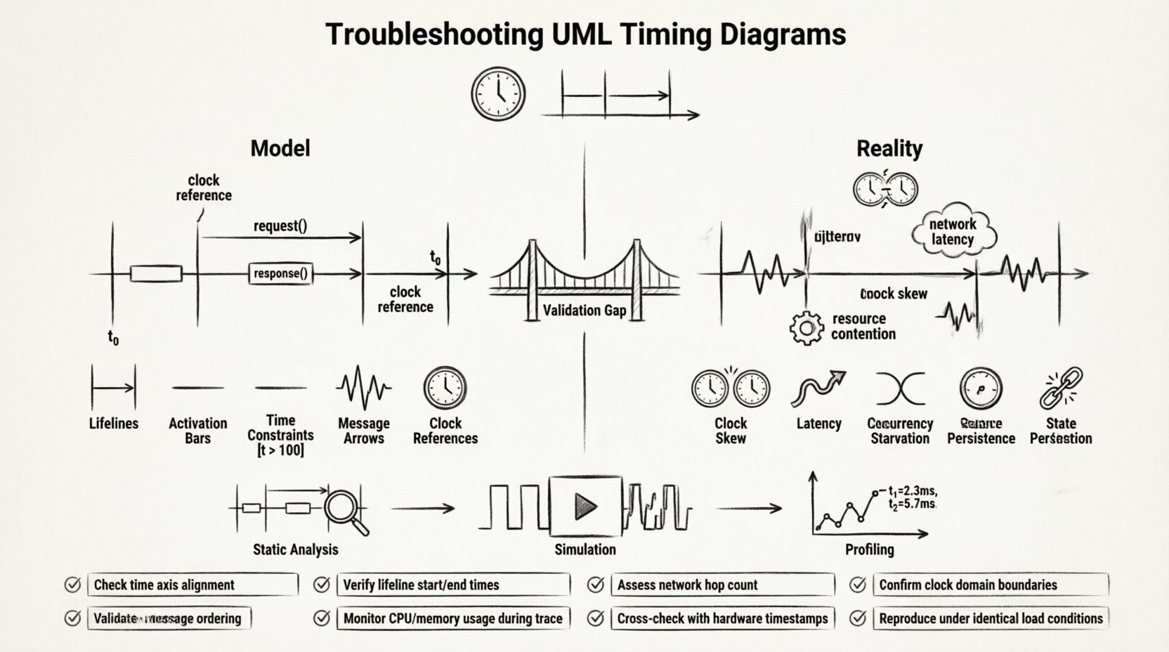
🛑 The Gap Between Abstraction and Execution
UML Timing Diagrams are abstract representations. They simplify complex physical realities into visual logic. A model assumes ideal conditions: zero network latency, deterministic clock cycles, and immediate resource availability. Reality rarely adheres to these assumptions. When you transition from the design phase to the deployment phase, the environment introduces noise.
- Hardware Variability: Different processors execute instructions at varying speeds.
- Network Jitter: Packet delivery times fluctuate in distributed systems.
- Resource Contention: Shared memory or CPU cores cause delays not predicted in isolation.
When your system behavior doesn’t match the model, it is often because the model failed to account for these environmental factors. Troubleshooting requires a shift from theoretical validation to empirical verification. You must treat the diagram not as a static document, but as a living hypothesis that needs constant testing.
🔍 Understanding the Timing Diagram Architecture
Before fixing errors, you must understand the elements that constitute a timing diagram. These diagrams differ from Sequence Diagrams by placing a heavy emphasis on the temporal axis. The horizontal axis represents time, while the vertical axis represents the lifelines of participating objects or processes.
1. Lifelines and Time Axes
Lifelines represent the entities involved in the interaction. In a timing context, each lifeline must have a defined clock or time reference. If two lifelines operate on different clocks, synchronization issues arise. You must ensure that the time units are consistent across the entire diagram. Mixing milliseconds with clock cycles without conversion leads to calculation errors.
2. Activation Bars
Activation bars indicate when an object is actively performing an action. In timing diagrams, the duration of these bars is critical. If the model shows an action lasting 5ms, but the hardware takes 10ms, the system fails. You need to verify the duration of every activation against the actual execution time of the corresponding code block.
3. Conditions and Guards
Conditions on the time axis define when a transition is allowed. These are often expressed as expressions like [t > 100]. If the model assumes a condition is met at t=100, but the system reaches it at t=105, subsequent events are delayed. This delay can cascade, affecting dependent processes.
4. Messages and Signals
Messages are the triggers that move the system from one state to another. In timing diagrams, the arrival time of a message is explicit. Troubleshooting often involves measuring the actual arrival time against the scheduled time. If messages arrive out of order, the model’s logic is invalid.
⚠️ Common Sources of Behavioral Mismatch
Identifying the root cause of a timing discrepancy is the first step in troubleshooting. There are specific categories of errors that frequently occur. Below is a breakdown of the most common sources.
| Category | Description | Impact |
|---|---|---|
| Clock Skew | Discrepancy between the clock sources of different components. | Desynchronization of parallel processes. |
| Latency Assumptions | Assuming network or bus latency is zero or constant. | Missed deadlines and timeout errors. |
| Concurrency Issues | Multiple threads accessing shared resources simultaneously. | Deadlocks or race conditions. |
| Resource Starvation | Insufficient CPU or memory available for the task. | Delayed execution of activation bars. |
| State Persistence | State not saved correctly between timing intervals. | Incorrect state transitions on restart. |
Clock Domain Crossing
One of the most frequent issues in hardware and low-level software modeling is clock domain crossing. If your system uses multiple clocks, timing diagrams must explicitly model the synchronization points. If the model assumes a single clock, but the implementation uses separate domains, the timing constraints become meaningless. You must account for the latency introduced by synchronizers.
Message Ordering
Timing diagrams often imply a strict order of events. In reality, network packets or inter-process messages may arrive out of order. If your model assumes message A arrives before message B, but the system receives B first, the logic flow breaks. This is common in asynchronous systems where delivery guarantees are not enforced.
Non-Deterministic Delays
Some system behaviors are inherently non-deterministic. Garbage collection, virtual memory swapping, and scheduling algorithms introduce variability. If your timing diagram uses fixed time values for these processes, the model will fail during stress testing. You must use ranges or worst-case execution times (WCET) instead of fixed values.
🛠️ Methodologies for Validation and Verification
Once you have identified potential sources of error, you need a method to validate the model against the system. Validation is not a one-time task; it is a continuous process throughout the development lifecycle.
1. Static Analysis of the Model
Before running any code, analyze the timing diagram for logical consistency. Check for deadlocks, infinite loops, or unreachable states. Ensure that all time constraints are mathematically feasible. If a task requires 10ms but the period is 5ms, the model is invalid regardless of the code quality.
- Check Dependency Chains: Ensure that no task depends on itself within the same time window.
- Verify Deadline Adherence: Confirm that the sum of execution times does not exceed the deadline.
- Analyze Resource Usage: Ensure that concurrent tasks do not exceed available resources.
2. Simulation and Emulation
Simulation allows you to run the model in a controlled environment. You can inject specific delays or faults to see how the system reacts. This helps isolate timing issues without affecting the production environment. Use simulation to test edge cases that are difficult to reproduce in real-time.
- Inject Latency: Add artificial delays to messages to test robustness.
- Stress Testing: Run the system at maximum load to observe timing degradation.
- Fault Injection: Simulate message loss or corruption to check recovery timing.
3. Profiling and Instrumentation
Instrumenting the code with timers and logs provides real-world data. Compare the logged timestamps against the model’s predictions. This data-driven approach reveals where the model deviates from reality. Look for patterns in the deviation. Is it consistent? Is it random? Does it happen under specific conditions?
- Trace Execution: Log the start and end time of every activation bar.
- Monitor Message Arrival: Record the exact timestamp of every incoming signal.
- Correlate Events: Map log entries back to specific elements in the timing diagram.
🔄 Aligning with Sequence and State Diagrams
A timing diagram does not exist in isolation. It is part of a larger UML suite. Inconsistencies often arise when the timing diagram conflicts with other diagrams. For example, a Sequence Diagram might show a logical flow, but the Timing Diagram shows a timing violation.
Consistency Across Diagrams
Ensure that the sequence of events in the timing diagram matches the logical flow in the sequence diagram. If the sequence diagram shows a decision point, the timing diagram must account for the time taken to evaluate that decision. Discrepancies between diagrams often indicate a misunderstanding of the system logic.
State Machine Integration
State diagrams define the states an object can be in. Timing diagrams define how long the object stays in those states. If the timing diagram implies a state change that the state machine does not support, a conflict occurs. You must synchronize the state transitions with the timing constraints.
Use Case Alignment
Finally, ensure that the timing requirements support the use cases. If a use case requires a response time of 200ms, the timing diagram must reflect this constraint. If the model allows for 500ms, the system will not meet user expectations. Align the timing constraints with the functional requirements.
📊 Diagnostic Checklist for Timing Anomalies
When troubleshooting, use a structured checklist to ensure no steps are missed. This list covers the critical areas where timing errors typically hide.
- ✓ Verify Clock Synchronization: Are all components using the same time reference?
- ✓ Check Message Ordering: Are messages arriving in the expected sequence?
- ✓ Validate Execution Times: Do actual run times match the model’s predictions?
- ✓ Inspect Resource Contention: Is there enough CPU or memory for the scheduled tasks?
- ✓ Review State Transitions: Do state changes happen within the allowed time window?
- ✓ Test Edge Cases: How does the system behave at the boundaries of the timing constraints?
- ✓ Analyze Network Load: Does high traffic affect message delivery times?
- ✓ Confirm Deadlines: Are all critical deadlines met under peak load?
🛡️ Long-term Maintenance Strategies
Even after you have resolved the initial discrepancies, timing models require maintenance. Systems evolve, and so do their requirements. A timing diagram that was accurate yesterday may be obsolete today.
Version Control for Models
Treat your diagrams as code. Store them in version control systems. This allows you to track changes over time and revert to previous versions if a new change introduces timing issues. Document every change to the timing constraints to maintain a clear history.
Automated Regression Testing
Implement automated tests that verify timing constraints. If a code change causes a timing violation, the test should fail. This prevents regression and ensures that the system remains compliant with the model. Integrate these tests into your continuous integration pipeline.
Regular Audits
Schedule regular audits of your timing diagrams. Review them against the latest system behavior. Update the model to reflect any changes in hardware, network, or software architecture. Keep the model as close to reality as possible.
🎯 Conclusion: Bridging the Model-Reality Divide
Troubleshooting UML Timing Diagrams is an exercise in precision and diligence. It requires a deep understanding of both the abstract model and the concrete system. By systematically validating constraints, analyzing discrepancies, and maintaining alignment with other diagrams, you can ensure that your system behaves as intended.
Remember that the goal is not perfection, but predictability. When your model and reality are aligned, you build trust. You create systems that are reliable, efficient, and robust. Use the strategies outlined here to diagnose issues, refine your models, and deliver high-quality software. The path to a synchronized system is paved with careful analysis and continuous verification.
Key Takeaways
- Validate Early: Check timing constraints during the design phase.
- Measure Often: Use profiling to compare model vs. reality.
- Document Changes: Keep your model up to date with system evolution.
- Test Edge Cases: Ensure robustness under stress and variation.
By following these practices, you transform your timing diagrams from static drawings into dynamic tools for engineering success. The difference between a working system and a failing one often lies in the details of time. Pay attention to them, and your system will perform reliably.