


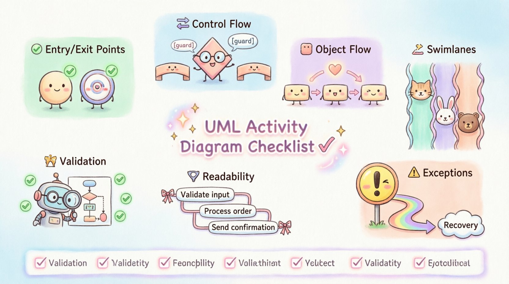
Creating a robust UML activity diagram is a critical step in the systems analysis and design process. These diagrams provide a visual representation of the workflow, capturing the logic and sequence of actions within a system. However, a diagram that is visually appealing but logically flawed can lead to significant misunderstandings during development. To prevent errors, a structured validation process is essential. This guide serves as a comprehensive checklist to verify that your activity diagrams are technically accurate, logically sound, and ready for implementation.
Whether you are modeling a simple business process or a complex concurrent system, the integrity of the control flow determines the reliability of the design. This resource breaks down the necessary components, from entry points to exception handling, ensuring every element serves a purpose. By following this detailed verification list, you can guarantee that your UML activity diagrams communicate the intended behavior without ambiguity. 🛠️
🚦 1. Entry and Exit Points: The Foundation
Every activity diagram must have a clear starting point and a defined endpoint. Without these anchors, the flow of control becomes ambiguous, leaving developers unsure where to begin execution or how to determine completion.
✅ Initial Node Verification
- Single Entry Point: Ensure there is exactly one initial node. Having multiple entry points can confuse the execution flow and complicate state management.
- Shape and Color: The initial node should be a solid filled circle. It must not contain any text labels directly on the circle itself, though it may have a note attached.
- Flow Direction: Verify that the flow moves outwards from the initial node. Inward flows to an initial node are invalid and indicate a logical error.
- Positioning: Place the initial node at the top or left of the diagram to align with standard reading conventions (top-to-bottom or left-to-right).
✅ Final Node Verification
- Defined Endpoints: Check if there is at least one final node representing the successful termination of the activity.
- Multiple Endpoints: It is acceptable to have multiple final nodes if different paths lead to different types of completion (e.g., success vs. cancellation), but ensure they are distinct.
- Shape: The final node is a solid circle surrounded by a ring (bullseye shape). Do not confuse this with the initial node.
- Reachability: Ensure every path in the diagram can eventually reach a final node. Deadlocks where flow stops without reaching an endpoint must be identified and resolved.
🔄 2. Control Flow and Logic: The Core Mechanism
The heart of an activity diagram lies in how control moves between actions. This section focuses on decision points, concurrency, and the merging of paths.
✅ Decision Nodes and Guards
- Diamond Shape: Verify that decision nodes are represented by a hollow diamond shape.
- Guard Conditions: Every outgoing edge from a decision node must have a guard condition. This is a boolean expression enclosed in square brackets, such as
[user is logged in]. - Completeness: Ensure all possible outcomes are covered. If a condition is not met, is there a default path? If not, the logic is incomplete.
- Uniqueness: Guard conditions on outgoing edges from the same decision node must not overlap in a way that creates ambiguity. Only one path should be valid at a time.
✅ Fork and Join Nodes
- Concurrency: Use fork nodes (a thick horizontal or vertical bar) to split the flow into parallel threads.
- Synchronization: Use join nodes to synchronize parallel threads back into a single flow.
- Matching: Ensure that every fork has a corresponding join. An orphaned thread that never joins creates a dangling process that may never complete.
- Logic Check: Verify that the join waits for all incoming branches. If a join is designed to merge but one branch never arrives, the system hangs.
✅ Merge Nodes
- Divergence Point: Use merge nodes to combine alternative paths that do not require synchronization.
- Distinct from Joins: Do not confuse merge nodes with join nodes. A merge combines options (A or B), while a join waits for options (A and B).
- Placement: Merge nodes should be placed logically where paths converge after different processing steps.
📦 3. Object Flow and Data: Handling Information
Control flow dictates the sequence of actions, but object flow dictates the movement of data. A complete diagram must account for how data is created, modified, and consumed.
✅ Object Nodes
- Representation: Object nodes are depicted as rectangles with the title Object Node above the name.
- Placement: Ensure object nodes are placed where data is produced or consumed. They should not be floating in space without incoming or outgoing flows.
- State vs. Flow: Differentiate between an object that represents a state of the system (often implicit) and an object node that represents a specific instance of data.
✅ Object Flows and Pins
- Input/Output Pins: Actions require pins to interact with object nodes. Check that every action consuming data has an input pin and every action producing data has an output pin.
- Flow Direction: Ensure object flows move logically from production to consumption. Arrows should point from the object node to the action node for input, and vice versa for output.
- Consistency: Verify that the type of data matches the action requirements. A process expecting a string should not receive a numeric object node without a conversion step.
🏊 4. Swimlanes and Partitions: Organizing Responsibility
Swimlanes are used to group activities based on responsibility. This could be a specific actor, a department, or a system component. Proper partitioning is crucial for understanding who does what.
✅ Partition Definition
- Clear Labels: Each swimlane must have a clear and unique label identifying the responsible entity.
- Completeness: Ensure all relevant entities involved in the process have their own swimlane. If an actor is missing, the diagram implies they have no role.
- Boundaries: Activities must reside entirely within a swimlane. An action cannot straddle two swimlanes unless it represents a handoff, which should be visually clear.
✅ Handoff and Communication
- Flow Across Lanes: Control flows that cross swimlane boundaries represent a handoff or communication between entities.
- Visibility: Ensure these transitions are not obscured. The arrow should clearly cross the boundary line.
- Logical Dependency: Verify that a swimlane does not depend on an action in a previous swimlane unless a flow connects them. A swimlane cannot execute actions without an incoming control flow.
⚠️ 5. Exception Handling and Edge Cases
A robust design anticipates failure. Activity diagrams should not only show the happy path but also how the system reacts to errors or unexpected inputs.
✅ Exception Flows
- Identification: Identify points where an action might fail (e.g., database connection loss, invalid input).
- Exception Nodes: Use exception nodes (often represented as a specific action or flow) to handle these failures explicitly.
- Recovery Paths: Determine if the system can recover. If not, the flow should lead to a final node indicating failure.
- Consistency: Ensure exception handling does not bypass critical validation steps elsewhere in the diagram.
✅ Guard Conditions on Edges
- Error Checks: Apply guard conditions to control flows that represent error states.
- Clarity: Use clear labels for these conditions, such as
[error occurred]or[timeout]. - Default Paths: Ensure there is a clear default path for when no specific guard condition is met.
📝 6. Readability and Standards
Even a logically perfect diagram is useless if it cannot be understood by stakeholders. Adhering to naming conventions and layout standards improves maintainability.
✅ Naming Conventions
- Verb-Noun Format: Action nodes should generally use a verb-noun format (e.g., Calculate Total, Send Email).
- Consistency: Use consistent terminology throughout the diagram. Do not mix Process, Handle, and Execute for the same concept.
- Descriptiveness: Labels should be descriptive enough to understand the action without external documentation.
✅ Layout and Aesthetics
- Orthogonal Lines: Control flows should use right-angle bends (orthogonal routing) rather than diagonal lines to reduce visual clutter.
- Minimal Crossing: Arrange nodes to minimize the number of lines crossing each other. Crossing lines increase cognitive load.
- White Space: Leave adequate spacing between nodes. Crowded diagrams are difficult to read and prone to errors during updates.
- Direction: Maintain a consistent flow direction (usually top to bottom) to aid navigation.
🧐 7. Validation and Consistency Check
Before finalizing the diagram, perform a holistic review to ensure the system behaves as expected under various scenarios.
✅ Walkthrough Simulation
- Trace Execution: Manually trace a path from the initial node to a final node. Confirm that every step is valid.
- Parallel Execution: Simulate concurrent flows to ensure synchronization points work correctly.
- Edge Cases: Test the diagram with extreme inputs to see if the logic holds.
✅ Structural Integrity
- No Orphans: Ensure no node is isolated from the main flow.
- No Infinite Loops: Check for loops that do not have an exit condition.
- Completeness: Verify that all requirements are mapped to specific actions in the diagram.
📊 Summary Checklist Table
Use this table as a quick reference during your review process. Mark each item as complete before considering the diagram finalized.
| Category | Check Item | Status | Notes |
|---|---|---|---|
| Entry/Exit | Single Initial Node exists | ☐ | |
| Entry/Exit | Final Node(s) reachable from all paths | ☐ | |
| Control Flow | Decision nodes have guard conditions | ☐ | |
| Control Flow | Fork nodes have corresponding Join nodes | ☐ | |
| Data Flow | Object nodes have input/output pins | ☐ | |
| Swimlanes | All responsible entities have lanes | ☐ | |
| Swimlanes | Control flows cross boundaries correctly | ☐ | |
| Exceptions | Error paths lead to defined endpoints | ☐ | |
| Standards | Action labels follow verb-noun format | ☐ | |
| Standards | No infinite loops or deadlocks | ☐ |
🔍 Final Thoughts on Diagram Integrity
Validating a UML activity diagram is not a one-time task but an iterative process. As requirements evolve, the diagram must be updated to reflect the current state of the system. By adhering to this checklist, you ensure that the visual model remains a reliable artifact for communication and development.
Focusing on the accuracy of control flow, data movement, and responsibility assignment creates a solid foundation for software engineering. A well-validated diagram reduces ambiguity, minimizes rework, and clarifies expectations among team members. Take the time to review each element rigorously. The effort invested in this validation phase pays dividends in the stability and maintainability of the final system. 🚀
Remember that the goal is clarity. If a stakeholder cannot understand the diagram without explanation, it requires refinement. Use this guide to audit your work, identify gaps, and ensure that every connection serves a logical purpose in the broader system architecture.