Activity diagrams serve as the backbone for visualizing the dynamic aspects of a system. While flow charts and state machines offer insights into behavior, activity diagrams specifically focus on the flow of control and data. At the heart of this flow lies the decision node. Understanding how control branches through a system is critical for accurate modeling. This guide explores the mechanics of decision nodes, the syntax of branching, and the nuances of guard conditions.
🔍 What is a Decision Node?
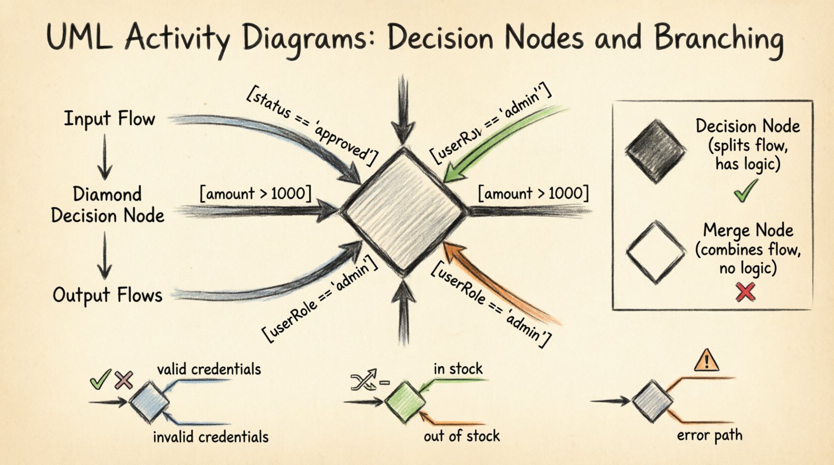
A decision node represents a point in the activity where the control flow diverges. It is visually depicted as a solid diamond shape. This symbol indicates that the process must choose a single path from multiple available options based on specific criteria. Unlike a merge node, which combines flows, a decision node splits them.
Every decision node requires at least one incoming flow and two or more outgoing flows. The selection of the outgoing path is determined by evaluating guard conditions attached to the outgoing edges. If no condition is specified, the flow is assumed to be unconditional, though this is rare in complex modeling.
- Input Flow: The single arrow entering the diamond.
- Output Flows: Multiple arrows exiting the diamond.
- Selection Mechanism: Logic evaluates conditions to pick one path.
- Concurrency: A single decision node does not create parallel flows; it selects one.
It is important to distinguish between control flow and object flow. A decision node acts on control. It decides whether an activity should proceed or which activity should execute next. It does not manipulate data objects directly, although the data may influence the decision logic.
🛡️ Understanding Guard Conditions
Guard conditions are the logical expressions that determine which path is taken. They appear on the outgoing edges of the decision node. These conditions must be written in a way that is clear and unambiguous to anyone reviewing the diagram.
Guard conditions are typically enclosed in square brackets. For example, [status == 'approved'] indicates that the flow proceeds only if the status is approved. If the condition evaluates to false, that path is not taken. The system looks for the first condition that evaluates to true.
Key Characteristics of Guard Conditions
- Boolean Logic: Conditions usually result in a true or false outcome.
- Exclusivity: In a standard decision node, only one path is selected per execution.
- Completeness: Ideally, conditions cover all possible scenarios to prevent deadlocks.
- Readability: Avoid overly complex boolean logic that obscures intent.
When modeling complex systems, guard conditions often reference object attributes or system variables. For instance, a warehouse process might check [inventory_level > 10] to determine if a shipment can be dispatched.
Examples of Guard Conditions
| Condition Syntax | Meaning | Example Context |
|---|---|---|
[amount > 1000] |
Amount exceeds threshold | Approval for large transactions |
[userRole == 'admin'] |
User has specific role | Access control permissions |
[status == 'pending'] |
Item is waiting | Workflow routing |
[!is_null] |
Value is not empty | Form validation |
🧭 The Syntax of Branching
Branching refers to the structural arrangement of paths emerging from a decision point. The standard UML notation uses a decision node for exclusive branching. This means only one path is active at a time.
When drawing these diagrams, attention must be paid to the labeling of the flows. Each outgoing edge should have a label indicating the condition. If a condition is false, the label is effectively skipped.
Exclusive vs. Inclusive Branching
Standard decision nodes imply exclusive branching. However, in some modeling scenarios, multiple conditions might be true simultaneously. In UML, this is handled via a merge node later, but the decision itself remains exclusive unless specified otherwise. To model inclusive branching where multiple paths activate, one typically uses a fork node followed by a decision node, or simply ensures the logic accounts for parallel execution.
For the purpose of standard activity diagrams, we assume exclusive branching unless a fork node is explicitly used. This distinction is vital for maintaining accurate performance and concurrency models.
- Exclusive Branching: One path only. The
if-elsestructure. - Parallel Flow: Multiple paths simultaneously. The
forkstructure. - Combination: Use a decision node to route, then a fork to parallelize.
🔄 Decision Node vs. Merge Node
These two nodes are often used in pairs. The decision node splits the flow, and the merge node combines it. Confusion between them can lead to significant modeling errors.
- Decision Node (Diamond): Splits one flow into many. Logic determines the path.
- Merge Node (Diamond): Combines many flows into one. No logic is applied here.
A merge node does not evaluate conditions. It simply waits for any incoming flow to arrive and passes control forward. The logic resides entirely at the decision point.
| Feature | Decision Node | Merge Node |
|---|---|---|
| Shape | Black Diamond | White Diamond |
| Input Flows | 1 (or more in complex cases) | 1 or more |
| Output Flows | 2 or more | 1 |
| Function | Route based on condition | Combine routes |
| Logic | Yes | No |
📋 Common Patterns & Examples
Applying these concepts requires practical examples. Below are common scenarios where decision nodes are essential for modeling.
1. User Authentication Flow
Consider a login process. After credentials are entered, the system must verify them. A decision node checks the validity of the username and password.
- Input: User submits login form.
- Decision: Is credential valid?
- Path A (True): Redirect to dashboard.
- Path B (False): Show error message.
This simple branching ensures users do not access protected areas without proper verification.
2. Order Processing System
In an e-commerce context, orders vary in size and inventory status. A decision node evaluates the order details.
- Decision: Is stock available?
- Branch 1: Yes → Process payment.
- Branch 2: No → Notify customer.
Furthermore, a second decision node might check the payment status. If payment fails, the order is cancelled. If it succeeds, the order is shipped. This nesting of decision nodes allows for complex business rules to be visualized clearly.
3. Exception Handling
Robust systems must handle errors. A decision node can check for null values or unexpected states before proceeding.
- Check: Is data valid?
- True: Proceed to processing.
- False: Log error and terminate or retry.
Using decision nodes for exception paths prevents the system from crashing when unexpected data is encountered.
🧠 Handling Complex Logic
As systems grow, decision nodes can become crowded. When a node has too many outgoing edges, readability suffers. In such cases, it is advisable to break down the logic into sub-activities or nested diagrams.
Strategies for Complex Branching
- Sub-Activity: Encapsulate a complex decision tree within a single activity box.
- Hierarchical Diagrams: Create a high-level overview and drill down into detailed logic in separate diagrams.
- State Tables: For highly complex logic, a state table might complement the diagram, though the diagram remains the primary visual tool.
Over-complicating a single decision node can lead to maintenance issues. Future developers may struggle to trace the logic if the diamond has ten outgoing paths. Keeping the branching factor low improves maintainability.
Nesting Decision Nodes
Sometimes, a decision must be made based on the result of a previous decision. This is known as nesting.
- Step 1: Check if user is logged in.
- Step 2: If yes, check if user is an admin.
This sequential checking ensures that the second condition is only evaluated when the first is true. It optimizes the process by avoiding unnecessary checks.
⚠️ Common Pitfalls to Avoid
Even experienced modelers can make mistakes. Awareness of common errors helps maintain diagram integrity.
1. Missing Paths
If a decision node has two outgoing paths, but only one is labeled with a condition, the other is assumed to be the default (false). However, if conditions are not exhaustive, the flow might halt. Every possible outcome should have a defined path.
2. Infinite Loops
Decision nodes can create loops. If a condition always evaluates to true, the process may cycle indefinitely. Ensure that loop conditions have an exit path.
3. Ambiguous Labels
Labels like [OK] or [Yes] are too vague. Use specific conditions like [status == active]. Ambiguity leads to misinterpretation of the system behavior.
4. Mixing Control and Object Flow
Do not use a decision node to split object flows. Object flows represent data movement. Control flows represent logic. Mixing them confuses the diagram semantics.
5. Deadlocks
A deadlock occurs when two or more activities wait for each other. Ensure that decision nodes do not create circular dependencies that prevent progress.
✨ Best Practices for Clarity
Clear diagrams communicate effectively. Follow these guidelines to ensure your activity diagrams are professional and understandable.
- Consistent Naming: Use standard terminology for conditions. Avoid colloquialisms.
- Visual Hierarchy: Arrange nodes to minimize line crossings. A clean layout aids comprehension.
- Swimlanes: Use swimlanes to indicate which actor or component is responsible for the decision. This clarifies ownership of logic.
- Documentation: Add notes for complex guard conditions. Explain the source of the data used in the condition.
- Review: Have peers review the diagram. Fresh eyes catch logical gaps that the creator might miss.
📊 Advanced Scenarios
Advanced modeling often involves integrating decision nodes with other UML elements.
Interaction with Object Nodes
Object nodes represent data. A decision node might inspect an object node to determine the path. For example, a node checks the orderStatus object attribute. This links the logic directly to the state of the data.
Interaction with Object Flows
While decision nodes control the flow, they often act upon object flows. The data moves through the system, and the decision node directs that data to different processing steps.
Concurrency Considerations
When using fork and join nodes alongside decision nodes, be careful about synchronization. A fork creates parallel threads. A decision node selects one path. Combining them requires ensuring that the control flow matches the object flow expectations.
🛠️ Implementation Considerations
When translating diagrams into code, decision nodes become conditional statements. A diamond in the diagram translates to an if or switch statement in the software.
- Guard Conditions: Become boolean expressions in code.
- Paths: Become branches in the code structure.
- Merge Nodes: Represent the point where branches recombine in execution.
Ensuring the code matches the diagram is crucial. Discrepancies between the design and the implementation lead to technical debt. Regular audits of the code against the activity diagram help maintain alignment.
📝 Summary of Key Concepts
Activity diagrams provide a robust way to model workflows. Decision nodes are the mechanism for introducing logic and branching. Guard conditions define the rules for these branches. Proper use of decision and merge nodes ensures that the model accurately reflects the system behavior.
By adhering to best practices and avoiding common pitfalls, you can create diagrams that are both technically accurate and easy to understand. These diagrams serve as a blueprint for development, communication, and maintenance.
- Decision Node: Splits flow based on logic.
- Merge Node: Combines flow without logic.
- Guard Condition: The rule determining the path.
- Flow: The movement of control and data.
Mastering the representation of control flow is essential for any system architect or analyst. These diagrams bridge the gap between abstract requirements and concrete implementation.