


UML activity diagrams serve as a critical bridge between abstract requirements and concrete implementation logic. They map out the flow of control within a system, visualizing the sequence of actions, decisions, and data transfers. However, as systems grow in complexity, these diagrams often become tangled webs of nodes and edges that obscure more than they reveal. When a diagram is difficult to read, it signals a breakdown in communication between architects, developers, and stakeholders. This guide provides a structured approach to identifying, analyzing, and resolving common issues found in complex activity diagrams.
Confusion in modeling often stems from a lack of standardization or the conflation of distinct UML concepts. Whether you are reviewing a legacy design or refining a new microservice workflow, understanding the nuances of control flow, object flow, and concurrency is essential. The following sections break down the specific technical areas where diagrams frequently fail, offering actionable strategies to restore clarity.
🧩 Understanding the Anatomy of Complexity
Before troubleshooting, one must understand the foundational elements that make up an activity diagram. Clarity begins with strict adherence to the UML standard regarding node types and connectors. Many confusion points arise from mixing semantic roles.
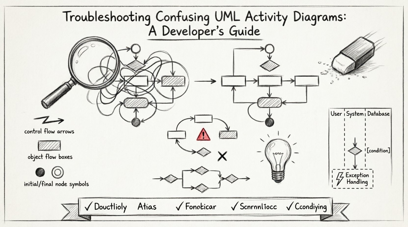
- Control Flow: Represents the order in which activities occur. It moves from one action to another based on completion conditions.
- Object Flow: Represents the movement of data or objects between activities. It does not dictate the order of execution directly but shows data dependency.
- Initial Node: The starting point of the activity. There should only be one initial node per top-level activity.
- Activity Final Node: Indicates the end of the entire activity. Control flows here when all logic is complete.
- Flow Final Node: Indicates the end of a specific flow path. Other paths may continue to their own final nodes.
A common error involves treating the Activity Final Node and Flow Final Node as interchangeable. Using an Activity Final Node in the middle of a diagram effectively halts the entire process, which is often not the intended behavior. Conversely, using a Flow Final Node to end a specific branch allows parallel branches to continue independently.
🔄 Common Flow Logic Errors
Logic errors in diagrams are often invisible until the code is written. A diagram might look syntactically correct but fail to represent the actual business rules. These issues typically manifest as deadlocks or unreachable states.
Deadlocks and Infinite Loops
A deadlock occurs when two or more flows wait for each other to complete, creating a cycle that never resolves. This is common when modeling concurrent processes that share resources without proper synchronization.
- Identify: Look for cycles where no exit path exists other than waiting.
- Solution: Ensure that every loop has a defined exit condition. Use guard conditions on decision nodes to force progress.
Unreachable Paths
Sometimes, a branch in the diagram is logically impossible to reach due to prior conditions. This creates noise and confusion for anyone trying to understand the full workflow.
- Identify: Trace the path from the initial node. If a decision node always routes to one side, the other side is unreachable.
- Solution: Remove the unreachable branch or adjust the guard conditions to make the path viable.
🏊 Managing Swimlanes and Partitions
Swimlanes are used to group activities based on responsibility, such as a specific actor, system component, or department. While helpful for organization, poor swimlane management can create visual clutter.
Over-Partitioning
Creating too many swimlanes breaks the flow of control across the page. It forces the reader to jump up and down the diagram to understand a single sequence of events.
- Guideline: Limit swimlanes to major functional boundaries. If a lane contains only one activity, consider merging it with an adjacent lane.
- Flow Crossing: Minimize the number of control flow lines crossing between swimlanes. Excessive crossing makes it difficult to track the process.
Inconsistent Naming
Labels on swimlanes must be consistent with the terminology used in the rest of the system documentation. Ambiguity in lane names leads to questions about which component is responsible for a specific action.
| Problem | Impact | Resolution |
|---|---|---|
| Generic Labels (e.g., “System”) | Low clarity on ownership | Use specific component names |
| Overlapping Responsibilities | Confusion on hand-offs | Define clear boundaries between lanes |
| Missing Labels | Cannot trace responsibility | Ensure every lane has a unique identifier |
⚡ Handling Concurrency and Parallelism
Modern systems often require parallel execution. UML represents this using Fork and Join nodes. Misusing these nodes is a primary source of confusion regarding timing and synchronization.
The Fork Node
A Fork node splits a single control flow into two or more concurrent flows. It does not imply time; it implies concurrency. All outgoing branches begin execution simultaneously upon arrival at the fork.
- Check: Ensure the fork node is connected to the activity preceding it. If it is not, the concurrency is not triggered correctly.
- Check: Verify that all outgoing flows from a fork are valid. Dead ends after a fork are common errors.
The Join Node
A Join node waits for all incoming flows to complete before allowing the outgoing flow to proceed. This is a synchronization point.
- Check: Ensure the join node receives all necessary parallel paths. If one path is missing, the flow will wait indefinitely.
- Check: Avoid using a join node if only one path is required to proceed. This is a Merge node, not a Join.
🚦 Decision Nodes and Merge Points
Decision nodes introduce branching logic based on conditions. Merge nodes combine multiple paths back into a single flow. These elements are crucial for representing business rules but often become messy.
Guard Conditions
Every outgoing flow from a decision node should ideally have a guard condition (a Boolean expression in square brackets). If a condition is missing, the reader must guess the logic.
- Requirement: All paths from a decision node must be mutually exclusive and collectively exhaustive.
- Requirement: Do not leave a path without a condition. Use “else” logic by placing a condition like [true] on the final path.
Completeness of Paths
A merge node expects all incoming paths to eventually lead to it. If a path branches off and never returns, it is a logic error. Conversely, if a merge node receives a path that does not align with the decision logic, the diagram is inconsistent.
🛡️ Exception Handling in Workflows
Standard workflows rarely go exactly as planned. A robust activity diagram must account for exceptions. However, exception handling is often buried or omitted, leading to incomplete models.
Activity Final vs. Flow Final
When an error occurs, does the entire activity stop, or just the current path? This distinction is vital.
- Activity Final: Stops everything. Use this for critical failures where the process cannot continue.
- Flow Final: Stops only this branch. Use this for optional steps or recoverable errors.
Interrupting Activities
Sometimes an activity is interrupted by an event before it completes naturally. UML allows for interruptible regions. These should be clearly marked to show where an exception can force a jump to an error handler.
- Visual Cue: Use a dashed box to denote the interruptible region.
- Trigger: Ensure the event that triggers the interrupt is explicitly labeled.
📋 Diagnostic Checklist for Diagram Review
When reviewing a diagram for confusion, use this checklist to systematically identify issues. This table helps standardize the review process.
| Category | Question to Ask | Pass/Fail |
|---|---|---|
| Start/End | Is there exactly one initial node? | Yes / No |
| Flow | Are all paths reachable from the start? | Yes / No |
| Logic | Do all decision nodes have guard conditions? | Yes / No |
| Concurrency | Do all forked paths join back correctly? | Yes / No |
| Swimlanes | Are responsibilities clearly separated? | Yes / No |
| Labels | Are activities and nodes named clearly? | Yes / No |
🧹 Refactoring Strategies for Clarity
Once issues are identified, refactoring the diagram is necessary. The goal is not to simplify the logic, but to simplify the representation of that logic.
Grouping and Sub-Activities
If a section of the diagram becomes too dense, encapsulate it into a sub-activity. This allows you to show the high-level flow in the main diagram and the detailed flow in a nested one.
- Benefit: Reduces visual noise on the parent diagram.
- Benefit: Allows different levels of detail for different audiences.
Naming Conventions
Consistent naming reduces cognitive load. Adopt a standard format for activities.
- Format: Verb + Noun (e.g., “Calculate Tax”, “Validate User”).
- Consistency: Do not switch between “Calculate” and “Calculation” for the same concept.
🔍 Real-World Pattern Recognition
Patterns emerge when reviewing multiple diagrams. Recognizing these patterns helps in predicting where confusion is likely to occur.
Serial vs. Parallel
Developers often model processes as serial when they should be parallel. If two actions do not depend on each other’s output, they should be forked. Serial modeling of independent tasks creates unnecessary bottlenecks in the visual representation.
Nested Activities
Deep nesting of activities creates a “spaghetti” effect where the flow is hard to trace. Limit the depth of nesting to two or three levels. If deeper, consider breaking the logic into separate diagrams.
🚀 Moving Forward with Better Modeling
Clear activity diagrams are not just about aesthetics; they are about precision. When a diagram is confusing, the implementation is likely to inherit that ambiguity. By adhering to strict UML standards, managing concurrency explicitly, and maintaining consistent swimlanes, you ensure that the model remains a reliable source of truth.
Regularly schedule diagram reviews using the checklist provided. Encourage team members to question every node and connector. This scrutiny prevents the accumulation of technical debt in the design phase. As the system evolves, the diagrams should evolve with it, maintaining their clarity and utility throughout the lifecycle of the software.