For many developers, the UML activity diagram begins and ends with a simple flowchart. You draw a start node, connect a few actions, and finish with an end node. While this serves a purpose for basic logic visualization, it falls short when modeling complex business processes, concurrent systems, or intricate data transformations. As a mid-level developer, understanding the nuanced patterns within activity diagrams is crucial for bridging the gap between abstract requirements and executable code.
This guide explores advanced patterns that transform a simple diagram into a robust modeling tool. We will cover concurrency, object flows, swimlanes, and exception handling without relying on specific software tools. The goal is to enhance clarity, reduce ambiguity, and improve communication within your team.
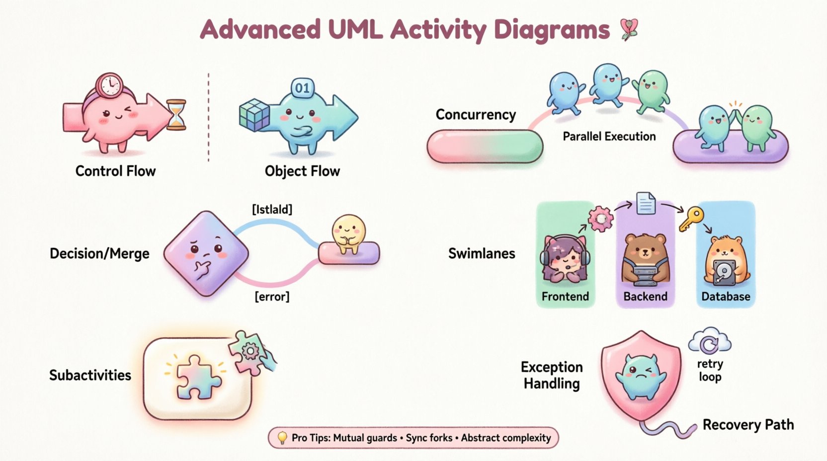
🔍 Control Flow vs. Object Flow
Before diving into advanced patterns, it is essential to distinguish between the two primary types of flows in activity diagrams: control flow and object flow.
- Control Flow: This represents the order of execution. It dictates when an action starts and stops. The arrows in a standard activity diagram typically denote control flow.
- Object Flow: This represents the movement of data or artifacts between actions. It shows how inputs are transformed into outputs.
Confusing these two can lead to significant implementation errors. When designing a payment processing system, for instance, control flow ensures the “Validate Card” action happens before “Charge Card.” Object flow shows that the “Card Data” object moves from “Validate Card” to “Charge Card.” Using both simultaneously provides a complete picture of system behavior.
⚡ Concurrency and Parallelism
Real-world systems rarely execute tasks in a strictly linear sequence. Concurrent processing is a common requirement. UML activity diagrams handle this through Fork and Join nodes.
1. The Fork Node
A fork node splits a single control flow into multiple concurrent flows. It looks like a thick horizontal or vertical bar. Once a token reaches the fork, the system creates multiple tokens, one for each outgoing edge. These tokens travel independently.
- Use Case: Sending a welcome email and an SMS notification simultaneously after user registration.
- Implementation Note: Ensure the subsequent actions can handle parallel execution without race conditions.
2. The Join Node
A join node waits for all incoming tokens to arrive before allowing the flow to continue. It looks identical to the fork node but functions inversely.
- Use Case: Only proceeding to “Send Confirmation” after both the “Email” and “SMS” tasks are complete.
- Implementation Note: If one branch takes longer, the join node holds the flow. This creates a synchronization point.
🤔 Decision and Merge Nodes
Logic branching is fundamental to programming. In activity diagrams, decision nodes represent points where the flow can take different paths based on a condition.
1. Decision Node
Visualized as a diamond, a decision node routes control to one outgoing edge. Each edge must have a guard condition (e.g., [isValid], [error]).
- Best Practice: Ensure guard conditions are mutually exclusive and collectively exhaustive to prevent deadlocks or undefined states.
- Example: If
[user exists]is true, go to “Login”; otherwise, go to “Register”.
2. Merge Node
A merge node combines multiple flows back into a single flow. It does not synchronize tokens like a join node; it simply accepts a token from any incoming edge.
- Use Case: Combining the “Success” and “Failure” paths of an API call back into a single logging action.
- Distinction: Unlike a join, a merge node does not wait for all branches. It passes through the first token that arrives.
🏊 Swimlanes and Responsibility
As systems grow, managing who does what becomes critical. Swimlanes (or partitions) organize activity diagrams by assigning actions to specific actors, roles, or subsystems.
- Vertical Swimlanes: Often used for departments or teams (e.g., Frontend, Backend, Database).
- Horizontal Swimlanes: Sometimes used for different phases or time periods.
Swimlanes improve readability by visually separating concerns. They make it immediately obvious where handoffs occur between different parts of the organization. A handoff from one lane to another often indicates a critical integration point or a potential failure zone.
Table: Swimlane Benefits
| Feature | Benefit |
|---|---|
| Visual Separation | Clearly distinguishes ownership of tasks. |
| Handoff Identification | Highlights where data crosses boundaries. |
| Complexity Reduction | Breaks a large diagram into manageable sections. |
| Accountability | Links specific actions to specific roles. |
🛡️ Exception Handling
Error handling is often overlooked in basic diagrams, but it is vital for robust systems. UML activity diagrams support exception handling through specific patterns.
- Exception Handler: You can attach an exception handler to an action. If the action fails, the handler is invoked.
- Compensation: In long-running transactions, if a step fails, you may need to roll back previous steps. This is modeled as a separate flow triggered by an exception event.
- Recovery: The diagram should show a path that attempts to recover the state, such as retrying a network request or switching to a backup service.
When modeling a file upload process, for example, include a decision node for “File Validated?” If no, trigger the “Log Error” and “Notify User” flows. If yes, proceed to “Save File.” This explicit modeling prevents the assumption that all paths succeed.
📦 Subactivities and Call Behavior Actions
Complex diagrams become unreadable if they contain too many details. Subactivities allow you to encapsulate a portion of the logic into a single action node.
- Call Behavior Action: This node represents a call to another activity diagram. It creates a modularity similar to functions in code.
- Refinement: You can expand the subactivity into a separate diagram to show the internal logic without cluttering the parent diagram.
This hierarchical approach is essential for maintaining large systems. It allows different team members to focus on specific sub-processes without needing to understand the entire system flow at once.
⚠️ Common Pitfalls and Mistakes
Even experienced modelers make mistakes. Below is a table highlighting common errors and their implications.
| Mistake | Consequence | Correction |
|---|---|---|
| Missing Join Nodes | Parallel flows never synchronize. | Ensure all forks have corresponding joins. |
| Overlapping Swimlanes | Confusion over task ownership. | Assign each action to exactly one lane. |
| Dangling Edges | Flow ends abruptly with no destination. | Ensure every edge leads to a node. |
| Excessive Detail | Digram becomes unreadable. | Use subactivities to abstract complexity. |
| Incorrect Guard Conditions | Logic paths become ambiguous. | Ensure all conditions are clear and exclusive. |
🔄 Integration with Development Lifecycle
Activity diagrams are not static documents; they are living artifacts that evolve with the codebase. Integrating them into the development lifecycle ensures they remain relevant.
- Design Phase: Use diagrams to validate logic before writing code. This catches logical errors early.
- Code Review: Reference the diagram to ensure the implementation matches the intended flow.
- Documentation: Keep the diagram updated as a reference for new team members.
- Testing: Use the diagram to derive test cases. Every branch in the diagram should correspond to a test scenario.
📈 Optimization and Refinement
As the system grows, the diagram may need optimization. Look for opportunities to simplify.
- Remove Redundancy: If multiple paths lead to the same action, consolidate them.
- Standardize Symbols: Ensure consistent use of diamonds, bars, and circles across all diagrams.
- Limit Depth: Avoid nesting subactivities too deeply. Three levels is usually the maximum for clarity.
- Focus on Value: Only model flows that add value to understanding the system. Ignore trivial details like variable initialization.
🤝 Collaboration and Communication
The true power of the activity diagram lies in its ability to facilitate communication. It serves as a shared language between developers, business analysts, and stakeholders.
- Business Alignment: Stakeholders can verify that the process matches business rules.
- Technical Feasibility: Developers can identify technical constraints early.
- Training: New hires can use the diagram to understand system workflows quickly.
When presenting these diagrams, focus on the story they tell. Explain the journey of the data and the responsibilities of the actors. Avoid getting bogged down in syntax. The goal is understanding, not just notation.
🔗 Advanced Object Flows
Object flows add a layer of data-centric modeling to the control-centric diagram. They show how data is created, consumed, and modified.
- Object Nodes: Represent the state of an object at a specific point in time.
- Pin: A small circle on the edge of an action where an object enters or exits.
- Read/Write: Indicate whether an action reads from or writes to an object node.
Consider a data migration process. The control flow ensures the steps happen in order. The object flow shows the data moving from the source database to the transformation service and finally to the destination database. This dual perspective is essential for data-heavy applications.
🧩 Handling Loops and Iterations
Loops are common in programming. In activity diagrams, loops are represented by a decision node that directs flow back to an earlier point.
- While Loop: Continue processing as long as a condition is met.
- For Loop: Iterate a specific number of times.
- Break/Continue: Use decision nodes to exit the loop early or skip to the next iteration.
When modeling a loop, ensure there is a clear exit condition. Infinite loops in diagrams suggest infinite loops in code, which are potential bugs. Always define the termination criteria explicitly.
🎯 Final Thoughts on Diagram Hygiene
Maintaining high-quality diagrams requires discipline. Regular reviews are necessary to remove obsolete paths and update logic. Treat the diagram as code; it needs version control and testing. By adhering to these advanced patterns and best practices, mid-level developers can create diagrams that are not just documentation, but essential tools for system design and communication.