
Mastering UML Activity Diagrams with VPasCode: Order Processing Workflows
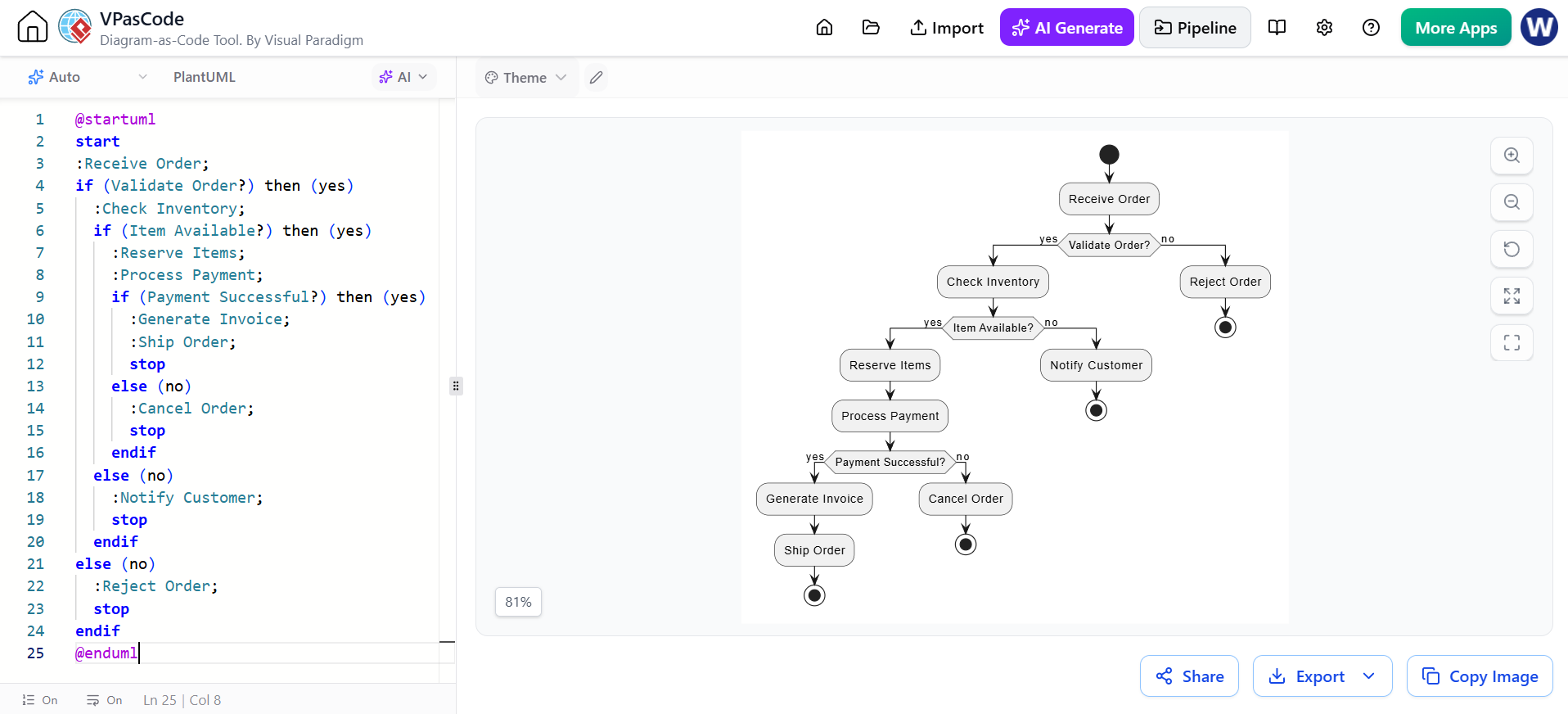
In the rapidly evolving landscape of software development, the ability to visualize complex business logic is just as critical as the code itself. This tutorial explores the practical application of Activity Diagrams using VPasCode, a powerful Diagram-as-Code tool by Visual Paradigm. We will deconstruct a real-world scenario—Order Processing—to demonstrate how developers can transition from abstract requirements to concrete visual models efficiently.
Introduction to Diagram-as-Code
Traditionally, creating UML diagrams involved drag-and-drop interfaces which, while intuitive, often lead to maintenance nightmares. Code changes require manual diagram updates, leading to discrepancies between documentation and reality.
Diagram-as-Code flips this paradigm. By writing plain text code (in this case, PlantUML) to generate diagrams, developers ensure that their visual documentation is:
- Version-Controlled: Diagrams can be stored in Git repositories alongside source code.
- Automated: Updates to the logic automatically update the visual representation.
- Accessible: Text files are easier to diff and review than binary image files.
Understanding the Order Processing Workflow
The example provided demonstrates a standard e-commerce transaction flow. This workflow is more than just a sequence of steps; it represents a decision tree that handles success paths and various failure scenarios.
1. The Entry Point: Receiving the Order
The workflow begins with the start node, immediately followed by the Receive Order action. In a real system, this corresponds to an API endpoint or a database trigger capturing customer data.
2. The First Gate: Validation
Before any resources are committed, the system must validate the incoming data. The diagram introduces its first decision point:
if (Validate Order?) then (yes)
If the order fails validation (e.g., invalid credit card, missing address), the flow branches to Reject Order and terminates. This is a crucial edge case handling step that prevents downstream processing errors.
3. Inventory Logic
Assuming the order is valid, the system moves to Check Inventory. This is a read-only operation to verify stock levels. A decision node checks if (Item Available?).
- Scenario A (No Stock): The system executes
Notify Customer. This is a vital business rule—customers must be informed immediately to manage expectations. - Scenario B (Stock Available): The system proceeds to lock the resources.
4. Financial Transaction & State Management
Once items are reserved, the system must process payment. This is the most critical step involving external dependencies (payment gateways). The workflow includes:
- Reserve Items: Temporarily deducting stock.
- Process Payment: Attempting a transaction.
- Payment Successful?: A final binary decision.
Detailed Breakdown of the VPasCode Syntax
VPasCode allows you to write this logic directly. Let’s analyze the specific PlantUML syntax used in the provided example.
Starting and Stopping
The flow is encapsulated by @startuml and @enduml. The process begins with start and ends with stop nodes. Notice that in this workflow, there are multiple stop nodes. This is a common pattern in Activity Diagrams to represent the termination of a specific thread or path (e.g., terminating the process upon rejection or successful shipping).
Nested Decision Blocks
The power of this code lies in its nesting. The structure allows for deep logic:
if (Payment Successful?) then (yes)
   :Generate Invoice;
   :Ship Order;
   stop
else (no)
   :Cancel Order;
   stop
endif
This block demonstrates how error handling is integrated directly into the logic flow. If payment fails, we don’t just stop; we explicitly execute a Cancel Order action before stopping, ensuring data integrity.
Best Practices for Modeling Complex Systems
When using VPasCode or similar tools, consider the following architectural principles:
1. Explicit Edge Cases
Don’t just model the “Happy Path” (where everything goes right). The example clearly shows paths for invalid orders, out-of-stock items, and failed payments. A robust system architecture diagram must account for failure.
2. Granularity of Actions
Notice the use of colons : to denote actions. Keep these actions atomic. For example, :Receive Order is a single step. Avoid combining steps like :Receive Order and Validate unless they happen instantaneously in a single atomic function.
3. Collaboration via OpenDocs
The context mentions sharing via OpenDocs. This is a game-changer for cross-functional teams. By sharing the diagram-as-code, operations teams and customer support can view the workflow logic without needing to install complex UML modeling software. They can even suggest changes directly in the code.
Conclusion
By utilizing VPasCode, developers move beyond static documentation. The Order Processing example illustrates how to build a resilient, fault-tolerant workflow model using simple text. Whether you are designing a microservice architecture or a monolithic application, mastering these activity diagrams ensures that your system logic is sound before a single line of production code is written.