
Mastering BPMN: A Guide to Avoiding Common Beginner Modeling Mistakes
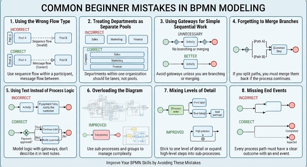
Business Process Model and Notation (BPMN) is the standard for visualizing business processes, yet even experienced modelers often struggle with the nuances of creating clean, accurate diagrams. For beginners, the challenge often lies in knowing when to use specific symbols and how to structure a process logically. This tutorial breaks down the eight most common pitfalls in BPMN modeling, providing clear “Incorrect” versus “Correct” examples to help you build robust system architectures.
1. The Foundation: Choosing the Right Flow Type
The most fundamental error in BPMN is confusing Sequence Flow with Message Flow. These two elements serve distinct purposes, and mixing them leads to confusion about where the process actually happens.
- Sequence Flow: This represents the order of activities within a single participant (a single Pool). It uses a solid line with an open arrowhead.
- Message Flow: This represents communication between participants. It uses a dashed line with an open arrowhead and connects to the boundary of a Pool.
graph TD
    subgraph PoolA [Pool A]
        A1[Start] --> A2[Activity A]
    end

    subgraph PoolB [Pool B]
        B1[Activity B] --> B2[End]
    end

    %% Correct Message Flow between pools
    A2 -.->|Message| B1
Why this matters
Using sequence flow between two separate pools implies that Pool A directly controls Pool B, which violates the principle of independent participants. Always use message flows to show hand-offs or notifications between different organizations or departments.
2. Organizational Structure: Pools vs. Lanes
Beginners often mistake every department for a separate “Pool.” In BPMN, a Pool represents a distinct participant (e.g., a different company, a client, or a completely separate entity). A Lane represents a role or department within a single organization.
- Incorrect Approach: Creating separate Pools for “Sales,” “Marketing,” and “Finance” implies these are three different companies. This creates a complex web of message flows where none exist.
- Correct Approach: Use one Pool for the “Company” and create Lanes for “Sales,” “Marketing,” and “Finance.”
graph TD
    subgraph Company [Company Pool]
        direction TB
        L1[Lane: Sales]
        L2[Lane: Marketing]
        L3[Lane: Finance]
    end
3. Logic vs. Decoration: The Gateway Trap
A gateway controls the flow of the process (branching or merging). It is not a decorative element to make a diagram look busy.
- Unnecessary Gateways: If you are simply moving from Step A to Step B, do not place a gateway between them. It adds visual clutter and implies a decision point that doesn’t exist.
- Correct Usage: Only use gateways when the path splits (e.g., “Is the user logged in?”) or converges (e.g., “Both paths finish here”).
4. Process Integrity: Merging Branches
When a process splits into different paths (e.g., Approve vs. Reject), it is a common mistake to leave those paths open-ended. If both paths eventually lead to the same activity (like a notification step), you must use a gateway to merge them.
graph TD
    Start((Start))
    Split{Split}
    PathA[Path A]
    PathB[Path B]
    Merge{Merge}
    Common[Common Step]
    End((End))

    Start --> Split
    Split -->|Yes| PathA
    Split -->|No| PathB
    PathA --> Merge
    PathB --> Merge
    Merge --> Common
    Common --> End
5. Text vs. Logic: Modeling Behavior
Text notes are useful for context, but they cannot execute logic. You cannot write a rule like “If payment fails, notify the customer” as a text annotation and expect the process to behave that way.
- Incorrect: Using a text box or a note to describe conditional logic.
- Correct: Use an Exclusive Gateway (XOR). This forces the modeler to define the “Yes” and “No” paths explicitly.
graph LR
    Activity[Process Order]
    Gateway{Payment Approved?}
    Success[Continue Order]
    Failure[Notify Customer]

    Activity --> Gateway
    Gateway -->|Yes| Success
    Gateway -->|No| Failure
6. Cognitive Load: Overloading the Diagram
A BPMN diagram is a communication tool, not a database dump. If a diagram contains too many details, it becomes unreadable. This is known as “diagram overload.”
To manage complexity, use the following techniques:
- Sub-processes: Encapsulate a complex set of steps into a single task box.
- Groups: Visually group elements without changing the flow.
- Separate Diagrams: Create a high-level overview (Level 1) and detailed drill-down diagrams (Level 2) for specific sub-processes.
7. Consistency: Mixing Levels of Detail
Consistency is key to readability. You should not place a high-level activity (like “Process Order”) right next to a granular step (like “Print Label”) unless they are part of the same logical sequence.
- The Problem: “Process Order” might take 5 minutes, while “Print Label” takes 10 seconds. Mixing these levels confuses the reader about the scope of the process.
- The Solution: Expand high-level tasks into sub-processes or remove granular steps to maintain a consistent abstraction level.
8. Completeness: Missing End Events
Every process path must have a clear conclusion. If a gateway splits the process into two paths, both paths must end.
- Incorrect: One path leads to a “Success” end event, while the other path simply trails off or loops back without a defined termination point.
- Correct: Every branch should explicitly define its outcome (e.g., Success, Rejected, Canceled, or Failed).
Recommended Tooling
To effectively apply these concepts and avoid the mistakes outlined above, you need a robust modeling environment. We recommend using Visual Paradigm BPMN. It offers a comprehensive suite of features specifically designed for BPMN 2.0 compliance, including automated layout algorithms and detailed error checking.
Furthermore, for advanced users looking to accelerate their workflow, integrating AI capabilities within Visual Paradigm can assist in generating diagrams from natural language descriptions and validating process logic automatically.