


The landscape of software architecture is shifting rapidly. For decades, engineers have relied on UML (Unified Modeling Language) to visualize system behavior. Among these diagrams, the Timing Diagram holds a specific, critical role. It captures the timing relationships between objects, signals, and events. As systems become more concurrent and distributed, the need for precise temporal modeling grows. Currently, creating these diagrams is a manual, labor-intensive process. However, new developments in artificial intelligence are changing how we approach this task.
Integrating AI-generated timing models offers a pathway to significantly faster prototyping. This guide explores the technical implications of this shift. We will examine how algorithms can interpret requirements to generate valid UML structures. We will also look at the validation mechanisms required to ensure these models remain accurate. The goal is to understand the mechanics of this integration, not just the hype.
Understanding the Core Mechanics of UML Timing Diagrams 📊
Before discussing automation, it is essential to understand the underlying structure of the artifact being generated. A Timing Diagram is a specialized view of a System State Machine or a Collaboration Diagram. It focuses on the behavior of instances over time.
- Time Axis: The horizontal axis represents time progression. It can be linear or non-linear depending on the specific modeling standard.
- Lifelines: Vertical lines represent instances or participants. These show the existence of an object over a duration.
- State Bars: Rectangular shapes along lifelines indicate the state of the object at specific intervals.
- Signal Events: Arrows crossing lifelines denote the transmission of messages or signals.
- Constraints: Time constraints define deadlines, periods, or intervals for specific actions.
Manual creation requires the engineer to calculate exact time intervals. If a system response must occur within 50 milliseconds, the engineer must place the event marker precisely. This manual calculation introduces a risk of human error. A slight misplacement can invalidate the entire timing logic of the protocol.
The Bottleneck of Manual Modeling 🛑
Traditional workflows for creating timing diagrams involve several distinct steps. Each step adds time to the project schedule.
- Requirement Analysis: Engineers read textual specifications to understand timing needs.
- Manual Drafting: Using drawing tools to place shapes on a canvas.
- Consistency Checks: Verifying that the timing matches the Sequence Diagram.
- Iteration: Updating the diagram when requirements change.
This process is iterative by nature. When a requirement changes, every dependent element must be adjusted. In complex systems with hundreds of interactions, this creates a maintenance burden. The cognitive load on the engineer is high. They must hold the entire temporal structure in their working memory while drawing.
AI Integration: How Algorithms Generate Models 🤖
Artificial Intelligence enters the workflow by automating the translation from text to visual structure. This is not merely pattern matching; it involves semantic understanding of system behavior.
1. Natural Language Processing for Requirements
Advanced models can parse engineering requirements documents. They identify keywords related to time, such as “delay,” “latency,” “timeout,” or “period.” These keywords are mapped to specific UML elements.
- Latency Detection: Phrases like “response within 100ms” trigger the creation of a specific time constraint on a signal arrow.
- State Identification: Descriptions of “active,” “idle,” or “processing” states are converted into state bars on lifelines.
- Sequence Extraction: The order of operations is extracted to determine the flow of events.
2. Pattern Recognition for Standard Behaviors
Many timing patterns are recurring in software engineering. Handshake protocols, polling loops, and interrupt handling follow predictable structures. AI models trained on existing repositories of valid diagrams can recognize these patterns.
When a new requirement matches a known pattern, the system suggests a pre-validated structure. This reduces the need for drafting from scratch. It ensures that common errors, such as deadlocks or race conditions, are less likely to appear in the initial draft.
Comparing Manual vs. AI-Assisted Workflows ⚖️
To understand the impact, we can compare the two approaches across key metrics.
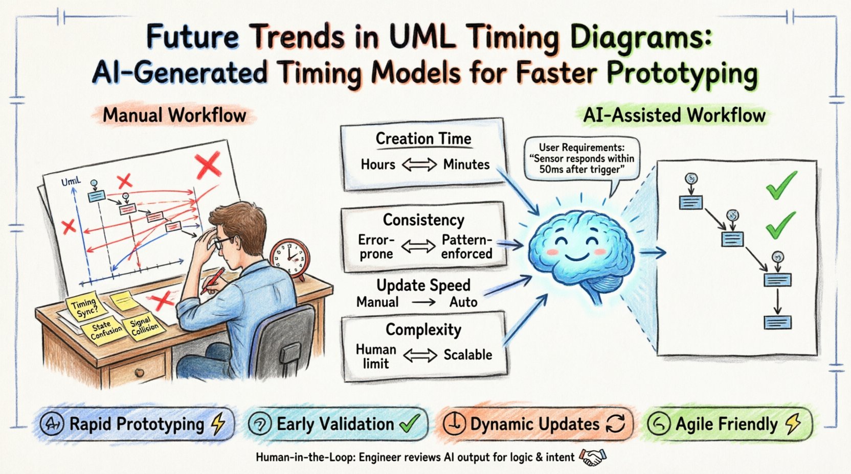
| Metric | Manual Approach | AI-Assisted Approach |
|---|---|---|
| Creation Time | Hours to Days | Minutes to Hours |
| Consistency | Prone to human error | High (Pattern enforced) |
| Update Speed | High effort for changes | Automated recalculation |
| Complexity Limit | Human cognitive limits | Scalable to large systems |
| Human Oversight | Full responsibility | Review and refinement |
This table highlights that the primary benefit is not just speed, but the ability to handle complexity. As systems grow, manual modeling becomes a bottleneck. AI tools allow the model to scale without a linear increase in engineering time.
Prototyping Speed and Iteration Cycles 🚀
The most immediate impact of AI-generated timing models is on the prototyping phase. Prototyping is about testing hypotheses quickly. If the model creation takes too long, the feedback loop slows down.
- Rapid Scenario Testing: Engineers can generate multiple timing scenarios to test edge cases. For example, what happens if the network latency doubles? The AI can adjust the time constraints and regenerate the diagram instantly.
- Early Validation: Since the model is generated from requirements, it can be reviewed before code is written. Discrepancies in timing logic are caught early.
- Dynamic Updates: When a deadline changes, the system recalculates the necessary buffer times. This keeps the documentation synchronized with the design.
This capability supports an agile development philosophy. It allows teams to pivot quickly without being held back by documentation overhead.
Validation and Consistency with Other Models 🔗
A generated diagram must not exist in isolation. It must align with Sequence Diagrams, State Machine Diagrams, and Activity Diagrams. AI integration must include a validation layer.
1. Cross-Reference Checking
The AI checks for consistency between diagrams. If a Sequence Diagram shows a message sent at time T, the Timing Diagram must reflect that signal at the corresponding point. Inconsistencies are flagged for human review.
2. Temporal Logic Verification
Algorithms can verify the temporal logic. They check for impossible conditions, such as an event occurring before its prerequisite. They also check for resource conflicts where two processes require the same resource at the same time.
3. Syntax Compliance
The generated output must adhere to the formal UML specification. Automated parsers ensure that the model can be exported to standard formats like XMI (XML Metadata Interchange) without errors. This ensures interoperability with other modeling tools.
Challenges in Implementation ⚠️
While the benefits are clear, there are technical challenges to consider. AI models are not infallible. They require careful implementation.
- Ambiguity in Requirements: Textual requirements can be vague. “Fast response” is not a precise number. The AI needs heuristic rules to interpret such terms, which may lead to suboptimal defaults.
- Context Loss: An AI might miss implicit context that an experienced engineer understands. For example, a specific hardware limitation might dictate a timing constraint that is not explicitly written in the text.
- Human Trust: Engineers must trust the generated model. If the model looks correct but contains a hidden logic error, it can lead to downstream bugs. Verification remains a critical step.
Best Practices for Adopting AI Modeling Tools 🛠️
To effectively integrate these technologies, teams should follow specific practices.
- Human-in-the-Loop: Treat AI as an assistant, not a replacement. Humans must review the generated diagrams for logical soundness.
- Standardized Inputs: Ensure requirements are written clearly. Use structured formats where possible to help the AI parse data accurately.
- Version Control: Store generated models in version control systems. This allows teams to track how the timing logic evolved over time.
- Iterative Refinement: Start with a basic AI-generated model and refine it manually. Use the AI to handle the bulk of the layout, leaving humans to focus on complex logic.
The Future of Temporal Modeling 🔮
Looking ahead, the integration of AI into UML modeling will deepen. We may see systems that simulate the timing behavior directly within the modeling environment. This means the diagram is not just a picture, but a runnable simulation.
- Predictive Modeling: AI could predict potential timing bottlenecks based on historical data from similar systems.
- Real-Time Synchronization: Models could sync with actual system performance data during testing. If the real system deviates from the model, the diagram updates automatically.
- Automated Code Generation: Valid timing models could drive the generation of stub code or test harnesses that enforce these constraints during development.
Technical Considerations for Data Formats 📁
For AI systems to work effectively, they need access to data. The standardization of UML data formats is crucial. Most modeling tools support XMI, which is an XML-based interchange format.
AI models can ingest XMI files to understand the structure of existing diagrams. They can then propose modifications or new additions. This backward compatibility ensures that legacy systems can benefit from new AI tools without requiring a complete migration.
Key Data Points for AI Analysis
- Event Timestamps: Exact points where signals are generated or received.
- Duration Constraints: Minimum and maximum times for process execution.
- Priority Levels: Which signals take precedence during contention.
- Resource Availability: When specific hardware or software resources are free.
Summary of Workflow Shifts 🔄
The shift from manual to AI-assisted timing diagram creation represents a fundamental change in the engineering process. It moves the engineer from a drafting role to a reviewing and optimizing role.
- Before: Engineer draws lines, calculates time, checks consistency manually.
- After: Engineer defines requirements, AI generates model, Engineer reviews logic.
This shift allows engineering teams to focus on high-level architecture and system behavior rather than the minutiae of drawing lines and calculating intervals. It reduces the risk of fatigue-induced errors and accelerates the path from concept to prototype.
Final Thoughts on Adoption 💡
Adopting AI-generated timing models requires a change in mindset. It is not about replacing the engineer. It is about augmenting their capabilities. The technology handles the tedious aspects of precision and layout. The engineer handles the nuance of logic and intent.
As these tools mature, they will become standard components of the engineering toolkit. The ability to visualize time accurately is a cornerstone of reliable system design. Automating this visualization ensures that reliability is maintained even as systems become more complex. The future of prototyping lies in the synergy between human expertise and algorithmic precision.
By understanding the mechanics of this integration, teams can prepare for a workflow where speed and accuracy coexist. The result is software that is built faster, validated earlier, and functions more reliably.