


Designing robust real-time systems requires precision. Every microsecond counts when safety, performance, and reliability are on the line. The Unified Modeling Language (UML) Timing Diagram is a specialized tool for visualizing the behavior of objects over time. It is crucial for embedded systems, communication protocols, and control loops. However, even experienced engineers often introduce subtle errors that invalidate the model.
These errors do not just look bad on paper; they lead to code that fails under load, missed deadlines, and unpredictable behavior in the field. Understanding the nuances of timing diagrams is essential for anyone involved in the specification or verification of time-critical software.
This guide explores the frequent pitfalls encountered when modeling time-dependent behavior. We will examine why these mistakes happen, their impact on system integrity, and how to correct them effectively. By adhering to strict modeling standards, you ensure your design remains verifiable and implementable.
1. Ambiguous Time Axis Scaling 📉
One of the most common issues is the lack of a consistent time scale. A timing diagram must represent time linearly to be mathematically verifiable. If the spacing between ticks changes arbitrarily, the visual representation becomes misleading.
- Non-Linear Spacing: Some diagrams compress early events and expand later ones to save space. This distorts the perception of latency and duration.
- Missing Units: Without explicit units (e.g., milliseconds, microseconds, cycles), the diagram is meaningless to the implementation team.
- Undefined Start Time: Failing to define T=0 makes it impossible to calculate absolute deadlines.
When the time axis is unclear, developers cannot determine if the system meets its real-time constraints. Verification tools cannot parse the diagram either. Always define a clear, linear scale with labeled units at the top of the diagram.
2. Lifeline Destruction Mismanagement 🗑️
Lifelines represent the existence of an object over time. A critical mistake involves neglecting to mark when an object is destroyed. In real-time systems, resources like memory, file handles, or network sockets are often finite. If a lifeline continues indefinitely, it implies the resource remains allocated.
- Missing X Marks: If an object should be cleaned up after a task, an “X” at the bottom of the lifeline is mandatory.
- Reused Lifelines: Creating new lifelines for every instance instead of reusing them can confuse the state machine logic.
- Overlapping Destruction: Destroying an object while it is still in an active state can lead to race conditions in the generated code.
Proper lifecycle management ensures that the model reflects the actual memory and resource usage of the system. This is vital for systems with limited RAM or strict garbage collection policies.
3. Message Sequencing and Causality ⚡
Timing diagrams must accurately reflect cause and effect. A message sent at time T1 cannot be received at time T0. However, many diagrams show messages overlapping in ways that violate causality.
- Simultaneous Causality: Depicting two events as happening at the exact same instant without defining the order can lead to ambiguity in implementation.
- Missing Activation Bars: Without activation bars (the rectangles on lifelines), it is unclear when an object is busy processing a message.
- Asynchronous vs. Synchronous: Confusing signal transmission with synchronous calls can lead to blocking issues in the final architecture.
To fix this, ensure that the horizontal position of every event strictly follows the flow of time. Use activation bars to show when a thread or process is occupied. This visual cue helps identify bottlenecks where the system is blocked waiting for a response.
4. Ignoring Concurrency and Parallelism 🔄
Real-time systems often run multiple threads or tasks simultaneously. A timing diagram that shows only a single thread of execution is often an oversimplification that hides critical race conditions.
- Single Thread Assumption: Modeling a multi-core processor as a single timeline ignores context switching overhead.
- Shared Resource Conflicts: Failing to show when two lifelines access the same variable or hardware peripheral can hide data corruption risks.
- Parallel Start Points: If two tasks start at the same time, the diagram must show parallel lifelines, not sequential ones.
When designing for concurrency, use multiple lifelines to represent independent tasks. Ensure that synchronization points (like mutexes or semaphores) are explicitly modeled. This allows engineers to analyze whether the system can handle the load without deadlock.
5. Vague Timing Constraints 🕒
Annotations are used to add specific timing requirements to events. A common error is using vague language like “as soon as possible” or “quickly”. These terms are subjective and cannot be tested.
| Bad Annotation | Impact | Correct Approach |
|---|---|---|
| “Fast Response” | Undefined behavior | “< 5ms” |
| “Within a second” | Ambiguous | “≤ 1000ms” |
| “Before next cycle” | Depends on cycle time | “< 100us” (if cycle is known) |
Always use numerical values for time constraints. If the value varies, use a range (e.g., “5ms to 10ms”). This precision allows for automated verification and simulation. Vague constraints lead to implementation guesses, which introduce bugs.
6. Overloading with Sequence Logic 📝
Designers often try to put too much logic into a timing diagram. They may include decision branches, loops, or complex data manipulation that belongs in a state machine or activity diagram.
- Complex Conditionals: Using “if/else” blocks that obscure the timing flow.
- Data Payloads: Focusing on the content of messages rather than their timing.
- Algorithmic Steps: Describing the internal processing steps of a function instead of the external interface timing.
Keep timing diagrams focused on temporal relationships. If the logic is too complex, split the diagram into multiple views or reference an external specification. A clean diagram is easier to validate than a dense one.
7. Missing Initial State ⚡
Every system has a starting point. A timing diagram that begins mid-process makes it impossible to understand the startup sequence. This is particularly dangerous for systems that must initialize hardware before running.
- Hardware Initialization: Skipping the power-up sequence can hide boot failures.
- Default Values: Failing to show the initial state of variables can lead to uninitialized memory bugs.
- Pre-conditions: Not showing the prerequisites for the first message can cause the system to hang.
Always start the diagram from the moment power is applied or the task is triggered. Show the initialization of the lifeline before the first interaction occurs. This ensures the model covers the entire lifecycle of the operation.
8. Inconsistent Object Instances 🏗️
Using different names for the same object across different diagrams causes confusion. For example, calling an object “Sensor” in one diagram and “TemperatureInput” in another breaks traceability.
- Naming Conflicts: Inconsistent naming makes it hard to link the diagram to the code.
- Type Mismatches: Showing a generic object where a specific class instance is required.
- Static vs. Instance: Failing to distinguish between shared static resources and local instances.
Standardize naming conventions across all diagrams. Use a glossary or a naming standard document. This consistency ensures that the model can be used as a source for code generation or verification without manual translation errors.
9. Ignoring Interrupts ⚠️
Real-time systems rely heavily on interrupts to handle external events. A timing diagram that only models the main loop ignores the asynchronous nature of interrupts.
- Interrupt Latency: Not showing the delay between the interrupt trigger and the handler execution.
- Priority Inversion: Failing to show when a high-priority interrupt preempts a low-priority task.
- Interrupt Nesting: Overlooking cases where one interrupt triggers another.
Include interrupt lifelines or separate diagrams for interrupt handling. Show the preemption clearly. This helps in calculating worst-case execution time (WCET), which is critical for safety-critical systems.
10. Lack of Boundary Definitions 🚧
Every system has inputs and outputs. A timing diagram that does not clearly mark the system boundaries can lead to integration issues.
- External Signals: Not distinguishing between internal messages and external inputs.
- Interface Contracts: Failing to show the timing of data entering or leaving the system boundary.
- Timeouts: Missing the definition of what happens if an external signal does not arrive.
Use distinct lifelines for external entities. Clearly mark the system boundary. Define what happens on timeout or error. This ensures that the system interacts correctly with the physical world or other software components.
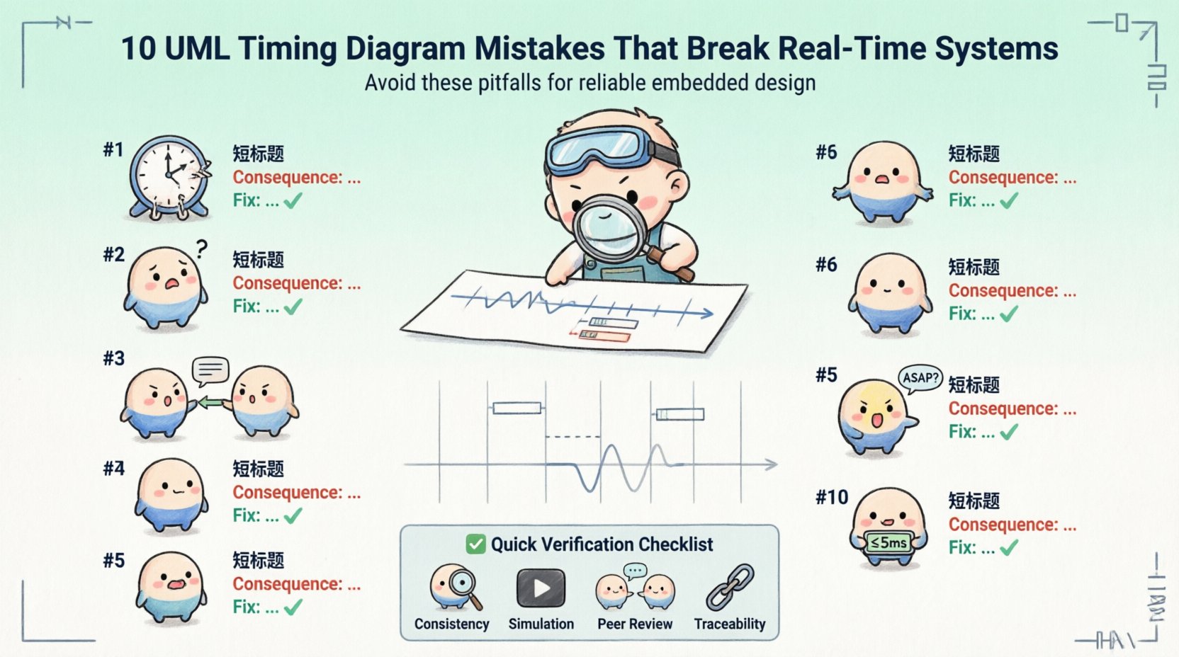
Best Practices for Verification ✅
Once the diagram is created, it must be verified. This process involves checking the model against the system requirements.
- Consistency Checks: Ensure the timing constraints in the diagram match the requirements document.
- Simulation: Run the diagram in a simulation environment to check for logical errors.
- Peer Review: Have another engineer review the diagram for clarity and correctness.
- Traceability: Link each element in the diagram back to a specific requirement ID.
Verification is not a one-time step. It should happen throughout the development lifecycle. As requirements change, the diagram must be updated to reflect the new reality. Keeping the model in sync with the code is the only way to ensure reliability.
Summary of Critical Errors 🛑
Avoiding these mistakes requires discipline and attention to detail. The table below summarizes the most critical errors and their corrections.
| Error Category | Consequence | Correction Strategy |
|---|---|---|
| Time Axis Ambiguity | Unverifiable constraints | Use linear scale with units |
| Lifeline Destruction | Memory leaks | Mark destruction points clearly |
| Causality Violation | Deadlocks | Ensure strict time ordering |
| Concurrency Ignored | Race conditions | Model parallel lifelines |
| Vague Constraints | Implementation errors | Use numerical values |
| Missing Interrupts | Missed deadlines | Include interrupt paths |
By following these guidelines, you create a model that serves as a reliable contract between design and implementation. A well-documented timing diagram reduces risk and improves the maintainability of real-time systems.
Focus on clarity, precision, and accuracy. These three pillars support the integrity of your design. When the diagram is correct, the code is more likely to be correct. Invest the time to get the timing right from the start.