Software architecture relies heavily on precise communication between components. When dealing with time-sensitive interactions, the UML Timing Diagram becomes an indispensable tool. However, many engineers treat these diagrams as mere afterthoughts or confuse them with sequence diagrams. This confusion often results in ambiguous requirements, unmanageable code, and a development cycle plagued by timing-related bugs. Understanding the nuances of timing constraints is not optional; it is a necessity for robust system design.
This guide explores the specific pitfalls that derail projects. We will examine how misinterpreting lifelines, ignoring message durations, and failing to document state changes can create a cascade of issues. By addressing these errors early, teams can prevent scope creep and reduce the time spent debugging elusive timing errors.
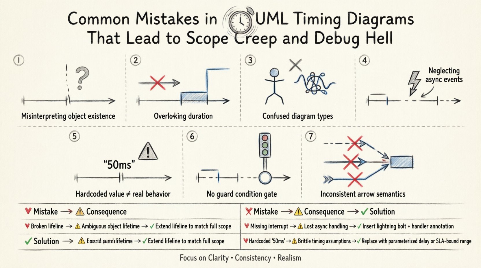
1. Misinterpreting Lifelines and Object Existence 🕰️
The foundation of any timing diagram is the lifeline. A lifeline represents an object or component over a period of time. A frequent error occurs when designers fail to distinguish between the creation of an instance and its active participation in a process.
- Assuming Constant Availability: Many diagrams imply that a component exists and is ready to respond at every timestamp. In reality, components may be in a sleep state, undergoing initialization, or experiencing resource contention.
- Ignoring Deactivation: If a lifeline remains active indefinitely without a clear end state, it suggests the object is always listening. This leads to memory leaks or unhandled thread states in the implementation.
- Confusing Logical vs. Physical Lifelines: A logical lifeline might represent a class, but a physical lifeline represents a thread or process. Mixing these without distinction causes synchronization errors.
When lifelines are not accurately defined, developers may allocate resources that are never released or fail to handle cases where a component is temporarily unavailable. This ambiguity forces the team to add logic to handle edge cases that were not anticipated in the design phase, directly contributing to scope creep.
2. Overlooking Message Duration and Activation Bars ⏱️
Activation bars indicate the period during which an object is performing an action. A critical mistake is treating messages as instantaneous events. In real-world systems, processing takes time. Ignoring the duration of an operation leads to race conditions.
- Instantaneous Messages: Drawing a message arrow with no duration implies the sender receives a response immediately. If the receiver requires significant processing, the sender may timeout or crash.
- Missing Overlaps: If two messages are scheduled to execute simultaneously on the same object without proper queuing, the system may exhibit undefined behavior.
- Ignoring Blocking: Some operations block the thread until completion. If the diagram does not show this blocking period, the architect may assume the thread is free to handle other tasks, leading to deadlocks.
By failing to model the width of activation bars accurately, the implementation team builds systems that cannot handle realistic latency. When performance bottlenecks arise, the blame often shifts to the code, when the root cause was a diagram that promised faster execution than the hardware could deliver.
3. Confusing Timing Diagrams with Sequence Diagrams 🔄
While both diagrams show interactions, they serve different purposes. A sequence diagram focuses on the order of messages. A timing diagram focuses on the time constraints and state changes of objects. Mixing these responsibilities creates confusion.
- Order vs. Time: A sequence diagram shows that Message B happens after Message A. A timing diagram shows that Message B must happen within 50 milliseconds of Message A.
- State Representation: Timing diagrams should explicitly show state changes (e.g., a state machine notation) along the lifeline. Sequence diagrams typically do not focus on this level of detail.
- Parallelism: Timing diagrams are superior for showing parallel processing paths. Sequence diagrams often flatten these interactions into a single timeline, hiding concurrency issues.
Using a sequence diagram for timing-critical logic forces developers to infer timing constraints that were never explicitly stated. This inference is a breeding ground for bugs. Developers make assumptions about latency and throughput, and when those assumptions fail, debugging becomes a nightmare.
4. Neglecting Asynchronous Events and Interrupts ⚡
Systems are rarely perfectly synchronous. External events, interrupts, and asynchronous callbacks occur unpredictably. A common mistake is modeling only the happy path in a linear fashion.
- Missing Interrupts: If a high-priority interrupt occurs, it may preempt a lower-priority task. If the diagram does not show this preemption, the scheduler implementation will be incorrect.
- Ignoring Timeouts: Every asynchronous call should have a timeout mechanism. Failing to mark the timeout period in the diagram leads to hung processes that consume system resources indefinitely.
- Event Queueing: How are events buffered? If the diagram shows events arriving faster than they can be processed, the system should show a backlog. Ignoring this leads to data loss in production.
Debugging asynchronous issues is notoriously difficult because they are non-deterministic. If the design does not account for the timing of these events, the code will struggle to maintain consistency. This often results in flaky tests that pass locally but fail in production environments with different load profiles.
5. Hardcoding Timing Constraints in the Design 📏
One of the most insidious errors is embedding specific time values (e.g., “50ms”) directly into the diagram without context. This creates a fragile design that cannot adapt to changing environments.
- Environment Dependency: A 50ms delay might be acceptable on a local server but unacceptable on a networked device with high latency. Hardcoding values ties the design to a specific infrastructure.
- Lack of Scalability: As the system scales, timing constraints often change. If the diagram is rigid, updating the design requires a complete rewrite of the documentation.
- Missing Variables: Instead of fixed values, use variables or parameters (e.g., Max_Latency). This allows the implementation to configure thresholds based on the deployment environment.
When constraints are hardcoded, the team loses flexibility. If the business requirement changes to support a new region with higher latency, the entire architecture must be re-evaluated. Good design separates the timing logic from the implementation details.
6. Failing to Document Guard Conditions 🚦
Timing diagrams often show a flow of events, but they frequently omit the conditions required for those events to occur. A message might only be sent if a specific state is reached. Without this context, the receiver is left guessing.
- Implicit Logic: If a message is sent only when
error_code == 0, this must be visible. If it is hidden, the developer might implement the message logic without the guard, causing errors. - State Transitions: Timing diagrams should align with state machine diagrams. If the diagram shows a message being sent, but the state machine says that state is unreachable, the design is contradictory.
- Complex Logic: Complex boolean expressions should be documented in notes attached to the message or lifeline. Relying on mental models of the logic is insufficient for complex systems.
When guard conditions are missing, developers write code that handles states that should never happen. This bloats the codebase and increases the surface area for bugs. It also makes the code harder to maintain because the logic for handling exceptions is scattered.
7. Inconsistent Notation and Standards 📝
UML is a standard, but teams often create their own variations. Inconsistent notation leads to misinterpretation among team members and stakeholders.
- Arrow Styles: Solid lines usually mean synchronous calls, while dashed lines mean asynchronous. Mixing these up confuses the execution model.
- Notation for Deadlines: Some teams use brackets, others use text. Consistency is key for automated parsing tools or documentation generators.
- Labeling: Messages should be clearly labeled with their purpose. Ambiguous labels like “Process Data” are insufficient. They should be “Validate Input” or “Save Record”.
Consistency reduces the cognitive load on the team. When everyone follows the same rules, reading a diagram takes seconds rather than minutes. This efficiency is critical when reviewing designs for potential timing issues.
Common Pitfalls vs. Correct Practices
The following table summarizes the most frequent errors and their corresponding solutions. Use this as a checklist during your design reviews.
| 🔴 Common Mistake | ⚠️ Consequence | ✅ Correct Practice |
|---|---|---|
| Assuming instantaneous messages | Timeouts and race conditions | Draw activation bars with realistic durations |
| Ignoring asynchronous interrupts | Deadlocks and resource leaks | Model preemption and queueing explicitly |
| Hardcoding specific millisecond values | Fragile design, poor scalability | Use variables or parameters for time constraints |
| Mixing sequence and timing logic | Ambiguous requirements | Use sequence for order, timing for constraints |
| Omitting guard conditions | Unnecessary code paths | Annotate conditions on message arrows |
| Inconsistent notation | Misinterpretation by team | Adopt and enforce a team-wide standard |
8. The Impact on Testing and Verification 🧪
A poorly designed timing diagram directly affects the testing strategy. If the diagram does not specify the timing constraints, testers cannot write effective tests for those constraints.
- Lack of Test Coverage: Without explicit timing goals, testers may focus on functional correctness and miss timing violations.
- Non-Deterministic Tests: If the timing is not modeled, tests may pass on one machine and fail on another due to hardware differences.
- Integration Issues: Timing mismatches between modules often surface only during integration. Early modeling catches these issues before code is written.
Investing time in accurate diagrams pays off during the testing phase. It allows for the creation of performance tests that validate the architecture against the design, rather than just the code.
9. Communication Barriers with Stakeholders 🗣️
Timing diagrams are not just for developers. They are often used to communicate with project managers and clients regarding system performance expectations.
- Managing Expectations: If the diagram shows a 1-second response time, but the implementation takes 5 seconds, trust is eroded. The diagram must reflect realistic capabilities.
- Scope Definition: Timing constraints define the scope. If a client asks for real-time performance but the diagram shows batch processing, the scope is mismatched.
- Change Management: When requirements change, the diagram must be updated immediately. Outdated diagrams lead to work being done that does not meet the new requirements.
Clear documentation prevents scope creep by making the boundaries of the system explicit. If a feature requires a timing constraint that is not modeled, it can be identified as out of scope early.
10. The Cost of Debugging Timing Issues 🐞
Debugging timing issues is significantly more expensive than debugging functional logic. You often cannot reproduce the issue easily because it depends on specific load conditions or race conditions.
- Reproduction Difficulty: If a bug occurs only when two threads interact within 10ms, reproducing it requires a controlled environment.
- Tooling Requirements: Debugging timing often requires specialized profilers or loggers, adding complexity to the development environment.
- Production Risk: Timing bugs often appear under load, meaning they might not be caught until the system goes live.
By preventing these mistakes in the design phase, teams save substantial resources. The cost of fixing a diagram error is negligible compared to the cost of fixing a deployed system with timing vulnerabilities.
Final Thoughts on Timing Accuracy 🎯
Creating accurate UML timing diagrams requires discipline and attention to detail. It is not enough to draw lines and arrows; one must understand the underlying behavior of the system. By avoiding the common pitfalls outlined in this guide, teams can build systems that are robust, maintainable, and performant.
Remember that the diagram is a contract between the design and the implementation. If the contract is vague, the implementation will suffer. Treat timing diagrams with the same rigor as functional specifications. This approach will save your team from the headaches of scope creep and the frustration of debug hell.
Focus on clarity, consistency, and realism. These three pillars will ensure that your timing diagrams serve their purpose effectively, guiding the development process toward success without unnecessary detours.