In the domain of safety-critical real-time systems, precision is not merely a preference; it is a requirement for survival. Whether designing automotive control units, medical devices, or aerospace avionics, the predictability of system behavior determines the safety integrity level. UML Timing Diagrams serve as a critical artifact in this ecosystem, visualizing the temporal relationships between events, signals, and object lifelines. However, a diagram that looks correct visually may fail to capture the rigorous constraints necessary for certification.
This guide provides a comprehensive framework for validating UML Timing Diagrams within safety-critical contexts. We focus on structural integrity, temporal accuracy, and traceability without relying on specific commercial tools. The goal is to ensure that the model reflects the physical reality of the hardware and software execution environment accurately.
📋 Why Validation Matters in Safety-Critical Environments
Safety standards such as ISO 26262 for automobiles and IEC 61508 for industrial systems mandate rigorous verification processes. Timing diagrams are often used to define worst-case execution times (WCET), interrupt latencies, and communication deadlines. If a timing diagram is flawed, the subsequent code generation or simulation will be incorrect, potentially leading to system failures that could harm users or the environment.
Validation differs from verification. Verification asks, “Are we building the product right?” (checking against the design). Validation asks, “Are we building the right product?” (checking against user needs and safety requirements). In the context of timing diagrams, validation ensures that the temporal constraints modeled actually align with the physical capabilities of the processor and the communication bus.
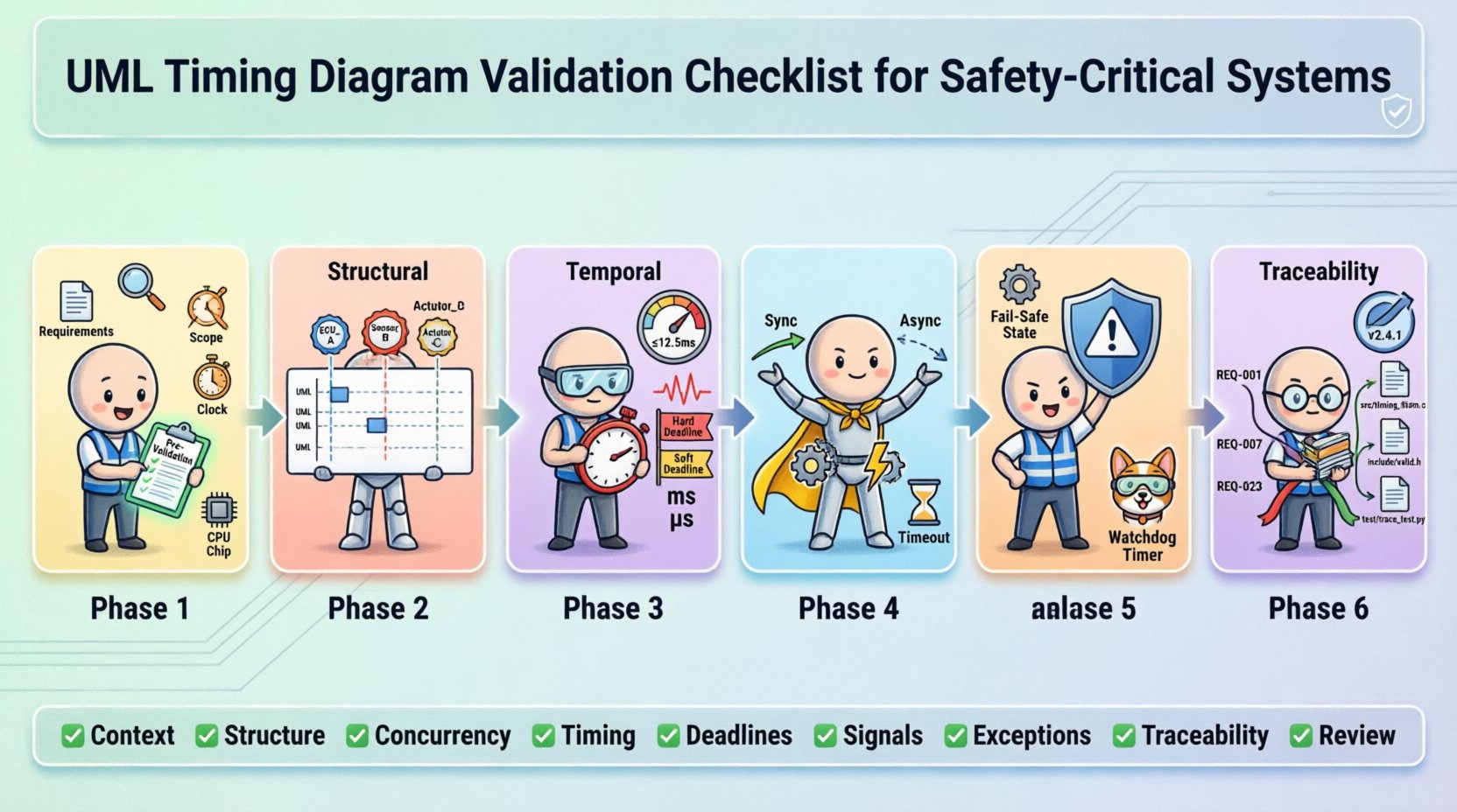
🔍 Phase 1: Pre-Validation Preparation
Before inspecting the diagram itself, the foundational context must be established. A timing diagram cannot exist in a vacuum; it relies on the behavior defined in state machines and the timing budget defined in system architecture.
- Requirement Alignment: Ensure every constraint on the diagram maps to a specific safety requirement. There should be no untraceable timing constraints.
- Context Definition: Define the scope of the diagram. Is it a single function, a subsystem, or the entire system? Clarity prevents scope creep and ambiguity.
- Time Reference Frame: Confirm whether time is absolute (wall-clock) or relative (since trigger). Mixing these without explicit markers leads to calculation errors.
- Execution Environment: Document the assumed processor speed, clock cycles, and interrupt priorities. The diagram must reflect the specific hardware configuration.
🏗️ Phase 2: Structural Validation
The structure of a UML Timing Diagram dictates how objects interact over time. Structural errors often lead to logical deadlocks or race conditions that are difficult to detect during testing.
2.1 Object Lifelines and Instance Names
- Uniqueness: Every lifeline must have a unique identifier. Duplicate names can confuse traceability tools.
- Consistency: Ensure the names match the system architecture documentation exactly. If the architecture calls it “Sensor_Module”, the diagram must not use “Sensor”.
- Activation Bars: Verify that activation bars (rectangles on lifelines) correctly represent the period of control. They should start when an operation is invoked and end when the operation returns or the signal is sent.
- Destroy Events: If an object is destroyed, ensure the “X” marker is placed correctly. Premature destruction can lead to null pointer exceptions in the generated code.
2.2 Region and Parallelism
Real-time systems often handle multiple tasks concurrently. UML allows this through combined fragments, specifically parallel regions.
- Parallel Regions: Verify that parallel regions (labeled with “par”) accurately represent hardware concurrency. Ensure that the parallelism matches the actual number of CPU cores or interrupt contexts available.
- Interference: Check for shared resources between parallel regions. If two parallel processes access the same memory address without synchronization, the diagram is unsafe.
- Guard Conditions: If guards are used within regions, ensure they are logically sound. A guard that is always true or always false defeats the purpose of the conditional flow.
⏱️ Phase 3: Temporal Validation
This is the core of timing diagram validation. Temporal errors are the most common source of non-determinism in safety-critical systems.
3.1 Timing Constraints and Values
- Units of Measure: Explicitly state the time unit (ms, us, cycles). Ambiguity here is a frequent cause of critical bugs.
- Range vs. Point: Safety-critical systems often require ranges (min/max). Ensure the diagram supports interval notation rather than fixed points where variation is possible.
- WCET Analysis: Every execution path shown must have a documented Worst-Case Execution Time. If a path is not analyzed, it cannot be represented in a certified diagram.
- Jitter: Account for jitter in communication. If a signal is expected every 10ms, allow for tolerance. The diagram should reflect the maximum allowable deviation.
3.2 Deadline Compliance
| Constraint Type | Validation Check | Safety Impact |
|---|---|---|
| Hard Deadline | Verify signal arrives before time T. | System Failure / Loss of Function |
| Soft Deadline | Verify signal arrives with minimal degradation. | Performance Degradation |
| Periodicity | Verify recurring intervals are constant. | Timing Drift / Oscillation |
| Latency | Verify response time from trigger to action. | Unstable Control Loop |
3.3 Time Expressions
- Complex Expressions: Avoid overly complex mathematical expressions in timing constraints. Keep them simple enough to be verified mathematically.
- Dependencies: If a timing constraint depends on another event (e.g., “Time = T1 + T2”), verify the dependency chain is closed and defined.
- Overflow: Ensure time values do not exceed the capacity of the underlying data types (e.g., 32-bit integers). This can cause wrap-around errors.
📡 Phase 4: Message Sequence & Interaction Validation
The flow of data determines the state changes. Incorrect message sequencing can lead to inconsistent system states.
4.1 Synchronous vs. Asynchronous Signals
- Arrow Types: Distinguish clearly between solid arrows (synchronous calls) and dashed arrows (asynchronous signals). Mixing them incorrectly implies blocking behavior where none exists.
- Return Values: For synchronous calls, ensure the return signal is accounted for. A missing return can cause the caller to hang indefinitely.
- Fire-and-Forget: For asynchronous signals, confirm that the sender does not wait for a response. This is crucial for non-blocking real-time tasks.
4.2 Lost or Duplicated Signals
- Communication Medium: Model the communication medium (bus, network, interrupt). Does the diagram account for message loss?
- Timeouts: If a signal might not arrive, is there a timeout mechanism modeled? A missing timeout is a common failure mode in safety systems.
- Retransmission: For critical messages, verify that retransmission logic is shown in the diagram if the protocol requires it.
⚠️ Phase 5: Exception Handling & Error States
Standard operation is only one part of the story. Safety-critical systems must handle failures gracefully.
- Exception Paths: Every operation should have an associated exception path. If a function fails, what happens to the timing?
- Recovery Time: Model the time required to recover from an error. This adds to the overall latency budget.
- Fail-Safe States: Ensure the diagram shows the system entering a safe state (e.g., stopping a motor) if timing violations occur.
- Watchdog Timers: Verify that the interaction with the watchdog timer is depicted. The system must reset if the diagram’s execution exceeds the watchdog limit.
🔗 Phase 6: Traceability & Documentation
A validated diagram is useless if it cannot be traced back to requirements or forward to implementation.
- Requirement Links: Every timing constraint should link to a requirement ID. This allows auditors to verify coverage.
- Implementation Mapping: Ensure the diagram maps to the actual source code functions. Function names in the diagram should match code signatures.
- Version Control: Timing diagrams evolve. Ensure versioning is managed to prevent using an outdated model for production code.
- Change Logs: Document why a timing constraint was changed. Was it due to a hardware change or a requirement update?
🛠️ Common Pitfalls to Avoid
Even experienced engineers fall into traps when modeling time. Be vigilant against these common issues.
- Ignoring Interrupt Latency: Assume the CPU is always available. In reality, interrupts can delay task execution by several microseconds. Model interrupt overhead.
- Over-Optimistic Timing: Use best-case scenarios instead of worst-case. Safety margins must be calculated based on the worst possible conditions.
- Ignoring Data Dependencies: Two tasks might be parallel, but if one depends on data from the other, they are effectively sequential. Model dependencies correctly.
- Static vs. Dynamic: Do not mix static timing analysis with dynamic simulation assumptions. They serve different validation purposes.
- Human Error in Manual Entry: If entering values manually, implement peer review. A single typo in a time value can invalidate the safety case.
🔄 Continuous Validation Strategy
Validation is not a one-time event. As the system evolves, the timing diagram must evolve with it.
- Regression Testing: When requirements change, re-run the validation checklist on the updated diagram.
- Hardware-in-the-Loop: Compare the diagram predictions against actual hardware performance. Discrepancies must be resolved.
- Periodic Review: Schedule regular reviews of the timing diagrams to ensure they still reflect the current system architecture.
- Automated Checks: If the modeling environment supports it, use scripts to validate syntax and basic constraints automatically.
📊 Summary of Validation Checklist
To ensure a robust safety-critical design, use the following summary as a quick reference during your review process.
- ✅ Context: Are scope and time units defined?
- ✅ Structure: Are lifelines and activation bars accurate?
- ✅ Concurrency: Are parallel regions hardware-accurate?
- ✅ Timing: Are WCET and jitter accounted for?
- ✅ Deadlines: Are hard and soft deadlines distinguished?
- ✅ Signals: Are synchronous and asynchronous signals clear?
- ✅ Exceptions: Are failure paths and timeouts modeled?
- ✅ Traceability: Are requirements linked to constraints?
- ✅ Review: Has the diagram been peer-reviewed?
Adhering to this comprehensive checklist ensures that your UML Timing Diagrams are not just graphical representations, but reliable blueprints for safe, deterministic real-time systems. By rigorously validating each element, you reduce the risk of runtime failures and align your design with the highest safety standards.
Remember that the diagram is a contract between the design and the implementation. If the contract is flawed, the execution will be flawed. Dedicate the necessary time and resources to this validation phase, as it is the foundation of system reliability.