


Introduction: Embark on Your UML Mastery Journey
- 🗂️ Structure complex systems before writing a single line of code
- 🤝 Align stakeholders—developers, designers, and business teams—around a shared visual blueprint
- 🔍 Identify design flaws early, saving time, resources, and technical debt
- 📚 Document architecture in a standardized, globally recognized notation
💬 “A picture is worth a thousand lines of code.”
Let’s turn your ideas into clear, actionable designs—together.
Welcome, traveler! This guide is designed as a personal learning journey. Each stage builds upon the last, helping you master UML Class Diagrams through clear explanations, visual examples, and practical application. Let’s begin your adventure!
🎯 Stage 1: Setting Your Compass — What Are We Modeling?
Before drawing diagrams, understand why we use them. The Unified Modeling Language (UML) is a standardized graphical notation for visualizing object-oriented systems. A Class Diagram specifically describes a system’s static structure by showing:
-
✨ Classes – The blueprints of your system
-
📋 Attributes – The data each class holds
-
⚙️ Operations/Methods – The behaviors classes can perform
-
🔗 Relationships – How objects connect and interact
💡 Journey Tip: Think of a Class Diagram as an architectural blueprint. You wouldn’t build a house without one—don’t build complex software without modeling its structure first!
🏗️ Stage 2: Understanding the Building Block — What Is a Class?
A Class is a blueprint for creating objects. Objects and classes are inseparable partners in Object-Oriented Design. While objects are the instances you interact with at runtime, classes define what those objects will be.
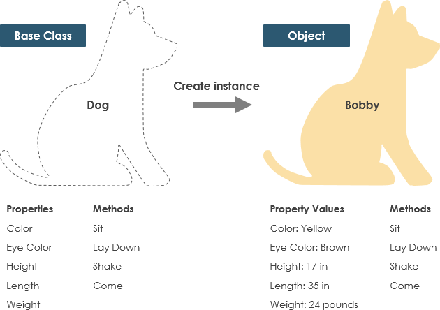
Real-World Analogy: The Dog Class 🐕
-
States (Attributes): color, name, breed
-
Behaviors (Operations): wagging(), barking(), eating()
Every Dog object created from this class shares the same structure but holds unique data. This separation of definition (class) from instance (object) is foundational to OOP.
📐 Stage 3: Mastering Class Notation — Speaking the Visual Language
A UML class is represented as a rectangle divided into three compartments. Only the class name is mandatory—attributes and operations can be added as needed based on your diagram’s perspective.
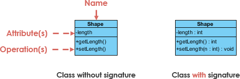
Compartment Breakdown:
-
Top: Class Name
The identifier. Bold and centered. -
Middle: Attributes
Format:visibility name: type
Maps to member variables in code. -
Bottom: Operations (Methods)
Format:visibility name(parameter: type): returnType
Maps to class methods in code.
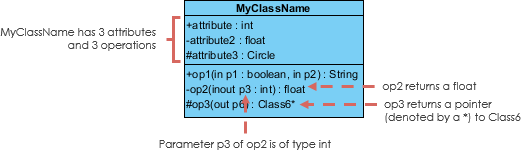
🔐 Controlling Access: Visibility Modifiers
Prefix attributes and operations with symbols to denote visibility:
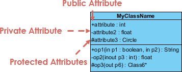
| Symbol | Visibility | Meaning |
|---|---|---|
+ |
Public | Accessible from any other class |
- |
Private | Accessible only within the class |
# |
Protected | Accessible within the class and its subclasses |
➡️ Parameter Directionality
For operations, specify parameter flow relative to the caller:
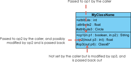
-
in– Value passed into the operation (default) -
out– Value returned to the caller -
inout– Value passed in and potentially modified
💡 Journey Tip: Start simple. In early conceptual diagrams, you might only show class names. Add detail as your design matures.
🔍 Stage 4: Choosing Your Perspective — How Deep to Go?
The level of detail in your Class Diagram depends on your development phase:
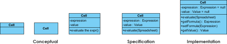
| Perspective | Focus | Best Used When |
|---|---|---|
| Conceptual | Domain concepts & relationships | Early analysis, stakeholder discussions |
| Specification | Interfaces & contracts (ADTs) | Defining APIs, component boundaries |
| Implementation | Concrete code structures | Final design, code generation |
🧭 Navigation Advice: Don’t overload early diagrams. A conceptual model with just class names and key relationships is often more valuable than a cluttered implementation spec during brainstorming.
🔗 Stage 5: Connecting the Dots — Class Relationships Deep Dive
Classes rarely exist in isolation. UML defines precise relationship types that translate directly to code patterns.
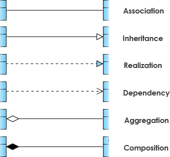
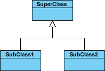
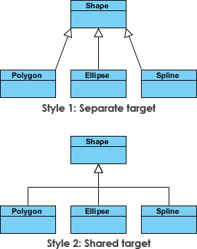
1️⃣ Inheritance (Generalization) — “Is-A”
Represents specialization. Subclasses inherit features from a superclass.
-
Solid line with hollow arrowhead pointing to parent
-
Abstract class names appear in italics
-
Example:
SquareandCircleinherit fromShape
2️⃣ Association — “Uses-A” / “Knows-A”
A structural link between peer classes.
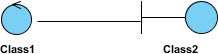
-
Solid line connecting classes
-
Often labeled with a verb phrase (e.g., “places”, “manages”)
📊 Cardinality (Multiplicity)
Defines how many instances participate:
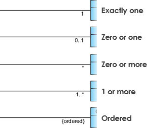
| Notation | Meaning | Example |
|---|---|---|
1 |
Exactly one | One Order has one Payment |
0..1 |
Zero or one | A User may have one Profile |
* or 0..* |
Zero or more | A Customer can place many Orders |
1..* |
One or more | An Order must have at least one Item |
3️⃣ Aggregation — “Has-A” (Weak Ownership)
A “part-of” relationship where parts can exist independently.

-
Solid line with unfilled diamond at the whole/end
-
Example: A
DepartmenthasProfessors, but professors exist if the department dissolves
4️⃣ Composition — “Owns-A” (Strong Ownership)
A stricter aggregation where parts cannot exist without the whole.
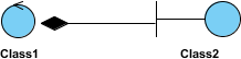
-
Solid line with filled diamond at the composite end
-
Example: A
Houseis composed ofRooms; destroy the house, rooms cease to exist
5️⃣ Dependency — “Uses-Temporarily”
One class uses another briefly (e.g., as a method parameter).
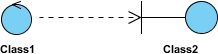
-
Dashed line with open arrow
-
Changes to the supplier may affect the client
-
Example:
Personhas ahasRead(Book)method—Persondepends onBook

6️⃣ Realization — “Implements”
Connects an interface (blueprint) to a class that implements it.
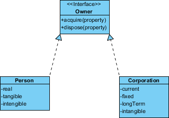
-
Dashed line with hollow arrowhead
-
Example:
PersonandCorporationboth realize theOwnerinterface
🧪 Stage 6: Applying Knowledge — Real-World Examples
📦 Example 1: Order Management System
See how classes, attributes, operations, and relationships combine in a practical domain:

Notice:
-
OrderaggregatesOrderItem(composition) -
Customerhas an association withOrder(1 to many) -
Paymentrealizes aPaymentMethodinterface
🖥️ Example 2: GUI Application with Notes
Class Diagrams can include explanatory notes for clarity:
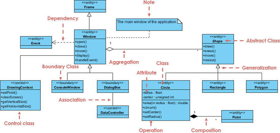
Tip: Use notes to document design decisions, constraints, or non-obvious relationships.
🚀 Stage 7: Your Toolkit — Practice & AI-Powered Assistance
You’ve learned the theory—now it’s time to create! Start with a free, powerful tool:
🎁 Get Visual Paradigm Community Edition
Free Download
An award-winning, intuitive UML modeler supporting all diagram types—completely free for learning and community use.
✨ Accelerate Learning with AI Assistance
Validate your understanding and generate diagrams faster using Visual Paradigm’s AI ecosystem:
Integrated Platforms
-
VP Desktop: Generate professional diagrams via AI, then refine with full-featured editing tools.
-
AI Chatbot: Draft and refine Class Diagrams instantly through natural conversation. Chat Interface
-
OpenDocs: Create dedicated Class Diagram pages or embed them directly into technical documentation.
Specialized AI Apps
| Tool | Purpose | Link |
|---|---|---|
| 🪄 AI Class Diagram Wizard | Step-by-step class building with AI-suggested attributes/operations | Launch Wizard |
| 📋 Use Case Studio | Auto-identify domain classes & relationships from use case text | Explore Studio |
| 🏃 Agilien | Generate Class Diagrams directly from Agile Epics & User Stories | Try Agilien |
| 🗄️ DB Modeler AI | Create conceptual Class Diagrams as DB schema foundations | Start Modeling |
| 🏗️ MVC Architecture Generator | Visualize Controller responsibilities in MVC systems | Generate MVC |
🌟 Final Journey Wisdom: Mastery comes through iteration. Sketch a simple diagram → get AI feedback → refine → repeat. Your confidence will grow with each cycle.
🏁 Conclusion: Your Journey Continues
🔑 Key Takeaways from Your Journey:
✅ Notation is flexible—show only the detail your audience and development phase require.
✅ Relationships tell the story—inheritance, association, aggregation, composition, dependency, and realization each map to precise code patterns.
✅ Perspective matters—conceptual, specification, and implementation views serve different purposes at different stages.
✅ Tools amplify learning—free software and AI assistants can accelerate practice, validation, and iteration.
🚀 What’s Next?
- Start small: Sketch a Class Diagram for a familiar domain (e.g., a library, e-commerce cart, or social media post).
- Iterate with feedback: Use AI tools or peer review to refine your diagrams.
- Integrate into workflow: Add Class Diagrams to your requirement docs, sprint planning, or onboarding materials.
- Teach others: Explaining concepts solidifies your own understanding—and elevates your team.
🌱 “The best time to model your system was at the start. The second-best time is now.”
Now go design something remarkable. 🎨✨
📚 Reference List
Unified Modeling Language: Comprehensive Wikipedia article explaining the Unified Modeling Language standard, its history, diagram types, and applications in software engineering and systems design.
Visual Paradigm Community Edition Download: Official download page for Visual Paradigm Community Edition, a free, award-winning UML modeling tool that supports all UML diagram types with an intuitive, user-friendly interface.
Visual Paradigm AI Chat Interface: Conversational AI chatbot that allows users to draft, refine, and validate UML Class Diagrams through natural language prompts and interactive feedback.
OpenDocs by Visual Paradigm: Platform for creating dedicated, shareable Class Diagram documentation pages or embedding interactive diagrams directly into technical project documentation and wikis.
AI Class Diagram Wizard: Dedicated step-by-step AI-powered wizard that helps users build UML classes with intelligent suggestions for attributes, operations, visibility, and relationships.
Use Case Studio: AI tool that automatically analyzes use case descriptions to identify relevant domain classes, attributes, and relationships, accelerating the transition from requirements to design.
Agilien: Agile-focused platform that bridges high-level planning (Epics, User Stories) to detailed design by generating implementation-ready Class Diagrams from Agile artifacts.
DB Modeler AI: AI-powered database modeling tool that creates conceptual Class Diagrams as the foundational layer for generating physical database schemas and SQL scripts.
MVC Architecture Generator: Specialized AI tool for generating Controller-focused Class Diagrams that visualize responsibility distribution and component interactions in Model-View-Controller architectural patterns.
🎉 Congratulations, Traveler!
You’ve completed your UML Class Diagram learning journey. You now possess the knowledge to read, interpret, and create professional Class Diagrams. Remember: great design is iterative. Keep modeling, keep refining, and let your diagrams tell the story of your system’s architecture. Happy designing! 🛠️✨