


A User Experience Guide from Beginner to Confident Modeler
🚀 Phase 1: Welcome & Orientation — What Is a Class Diagram?
You just opened your UML modeling tool. What now?
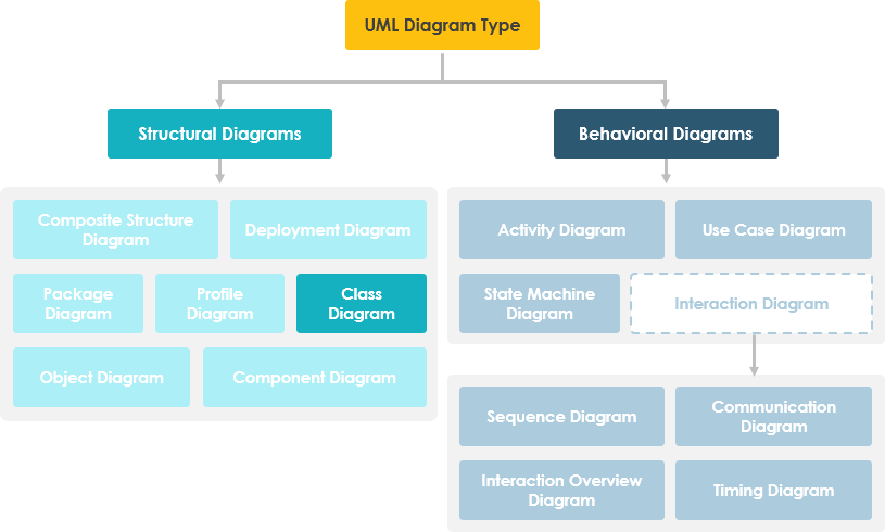
A UML Class Diagram is a static structure diagram that describes your system by showing:
-
📦 Classes: The blueprints of your objects
-
🔖 Attributes: What objects “know” (their state)
-
⚙️ Operations/Methods: What objects “can do” (their behavior)
-
🔗 Relationships: How objects connect and interact
Why Should You Care?
✅ Visualize system architecture before coding
✅ Communicate design decisions with your team
✅ Bridge business requirements and technical implementation
✅ Serve as living documentation that evolves with your product
🧱 Phase 2: Building Blocks — Understanding Classes
What Is a Class?
A class describes a group of objects with similar roles. Think of it as a template for creating objects in your system.
A Class Has Two Core Aspects:
| Aspect | Purpose | Maps To Code As |
|---|---|---|
| Structural Features (Attributes) | Define what objects know — their state/data | Member variables, fields, properties |
| Behavioral Features (Operations) | Define what objects can do — their actions | Methods, functions, procedures |
Class Notation: The Three-Part Box

┌─────────────────┐
│   ClassName     │ ← Partition 1: Class Name
├─────────────────┤
│ +attr1: Type    │ ← Partition 2: Attributes
│ -attr2: Type    │    • Type shown after colon
│ #attr3: Type    │    • Visibility symbols: + - # ~
├─────────────────┤
│ +op1(): Return  │ ← Partition 3: Operations
│ -op2(p:Type):R  │    • Parameters & return types shown
│ #op3(): Type*   │    • * denotes pointer/reference
└─────────────────┘
Reading the Example Above:
-
MyClasshas 3 attributes and 3 operations -
op2takes parameterp3of typeintand returns afloat -
op3returns a pointer (*) toClass6
💡 Pro Tip: Keep class diagrams focused. One class = one responsibility. If a class box gets too crowded, consider refactoring.
🔗 Phase 3: Making Connections — Class Relationships
Classes rarely exist in isolation. Relationships show how they collaborate.
The 5 Core Relationship Types
| Relationship | Meaning | Visual Notation | When to Use |
|---|---|---|---|
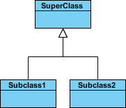
| Inheritance (Generalization) | “Is-a” relationship | Solid line + hollow arrowhead → | Modeling taxonomies, polymorphism |
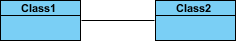
| Simple Association | Structural link between peers | Solid line connecting classes | Objects that interact or reference each other |
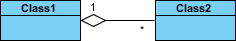
| Aggregation | “Part-of” with independent lifetimes | Solid line + unfilled diamond ◇ | Collections where parts can exist alone |
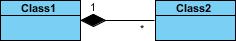
| Composition | “Part-of” with dependent lifetimes | Solid line + filled diamond ◆ | Strong ownership; parts die with whole |
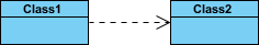
| Dependency | “Uses” relationship (weak coupling) | Dashed line + open arrow ⇢ | One class temporarily uses another |
Visual Reference:
Enhancing Relationships: Names, Roles & Navigability

-
Relationship Names: Write them mid-line for clarity
→ “Spreadsheet contains Cell” reads naturally -
Roles: Label ends of associations to show purpose
→ “Cell” has role “formula” pointing to “Expression” -
Navigability Arrows: Show direction of access
→ Given aSpreadsheet, you can find itsCells(but not necessarily vice versa)
🎯 User Insight: Add names and roles only when they improve clarity. Over-labeling creates visual noise.
🔐 Phase 4: Refining Details — Visibility & Multiplicity
Controlling Access: Visibility Modifiers
UML uses symbols to denote who can access attributes and operations:
| Symbol | Visibility | Accessible By |
|---|---|---|
+ |
Public | Any class |
- |
Private | Only the class itself |
# |
Protected | The class and its subclasses |
~ |
Package | Classes in the same package/module |
Access Rights Matrix:
| Access Right | Public (+) | Private (-) | Protected (#) | Package (~) |
|---|---|---|---|---|
| Same class members | ✅ | ✅ | ✅ | ✅ |
| Derived class members | ✅ | ❌ | ✅ | ✅ |
| Other classes | ✅ | ❌ | ❌ | ✅ if same package |
Expressing Quantity: Multiplicity
How many objects participate in a relationship?
| Notation | Meaning | Example |
|---|---|---|
1 |
Exactly one | A Car has exactly 1 Engine |
0..1 |
Zero or one | A Person may have 0 or 1 Spouse |
* or 0..* |
Many (zero or more) | A Library has many Books |
1..* |
One or more | An Order has at least 1 Item |
3..4 |
Exact range | A Team has 3 to 4 Coaches |
0..1, 3..4, 6..* |
Complex sets | Any quantity except 2 or 5 |
Multiplicity in Action:

Scenario: A Student can take many Courses; many Students can enroll in one Course.
→ The class diagram (left) defines the rule; the object diagram (right) shows a snapshot of actual enrollments.
🌐 Phase 5: Real-World Patterns — Examples That Stick
Example 1: Aggregation — Computer and Parts

-
ComputeraggregatesCPU,Memory,Storage -
Parts can exist independently (unfilled diamond ◇)
-
Models a “consists-of” hierarchy without strong ownership
Example 2: Inheritance — Cell Taxonomy

-
Shapeis an abstract superclass (italic name) -
Circle,Rectangle,Polygoninherit common attributes/operations -
Enables polymorphism: treat all shapes uniformly
Example 3: Full Diagram Walkthrough

Reading This Diagram:
-
Shapeis abstract (italic) — cannot be instantiated directly -
Circle,Rectangle,PolygonspecializeShape(inheritance) -
DialogBox↔DataController: simple association -
Window◇–Shape: aggregation (Shape can exist without Window) -
Circle◆–Point: composition (Point dies with Circle) -
Window⇢Event: dependency (Window uses Event) -
Circleattributes:radius: float,center: Point -
Circleoperations:area(): double,circum(): double,setCenter(),setRadius() -
Grey notes provide supplemental context without cluttering classes
💡 Pattern Recognition: Notice how composition (
◆) implies stronger lifecycle coupling than aggregation (◇). Choose deliberately.
🧩 Phase 6: Scaling Up — Managing Complex Systems
One Diagram or Many?
❓ “Should I model my entire enterprise system on one class diagram?”
Answer: 🚫 No — use multiple focused diagrams.
Why Multiple Diagrams Win:
✅ Cognitive Load: Humans process ~7±2 concepts at once
✅ Stakeholder Alignment: Business analysts see domain concepts; devs see implementation details
✅ Maintainability: Update one module without redrawing the universe
✅ Tool Performance: Large diagrams slow down modeling tools
Strategy: Slice by Concern
-
Domain Layer: Business entities and rules
-
Application Layer: Use cases and services
-
Infrastructure Layer: Persistence, APIs, external systems
-
Cross-Cutting: Logging, security, configuration
🎯 Pro Practice: Link diagrams with package dependencies or notes to maintain system-wide coherence.
🔄 Phase 7: Evolving with Your Project — Class Diagrams Across the SDLC
Class diagrams adapt to your development phase. Model at three progressive perspectives:
1️⃣ Conceptual Perspective (Early Discovery)
-
Focus: Real-world domain concepts
-
Audience: Business analysts, product owners, stakeholders
-
Language: Platform-agnostic, business vocabulary
-
Example:
Customer,Order,Product— no technical details
2️⃣ Specification Perspective (Design Phase)
-
Focus: Software abstractions and interfaces
-
Audience: Architects, senior developers
-
Language: Technology-neutral but software-aware
-
Example:
IOrderService,PaymentGateway— contracts without implementation
3️⃣ Implementation Perspective (Coding Phase)
-
Focus: Concrete classes in a specific language/framework
-
Audience: Developers, QA engineers
-
Language: Java, C#, Python syntax; framework conventions
-
Example:
OrderServiceImpl extends BaseService implements IOrderService
🌟 Key Insight: Start conceptual, refine to specification, finalize with implementation. Never skip levels — each builds essential shared understanding.
🤖 Phase 8: Accelerating Your Workflow — AI-Powered Class Diagramming
Why Start from Scratch? Let AI Help.
Visual Paradigm’s AI ecosystem transforms requirements into structured diagrams — faster, smarter, with fewer errors.
Multi-Platform AI Support:
| Platform | Best For | Key Capability |
|---|---|---|
| VP Desktop | Precision modeling | Generate diagrams via AI, then refine with professional tooling |
| AI Chatbot | Rapid ideation | Describe your domain in natural language → get instant class structures |
| OpenDocs | Living documentation | Embed AI-generated diagrams directly into interactive docs |
Specialized AI Tools:
⚡ AI Class Diagram Wizard
→ Step-by-step assistant for defining classes, attributes, and operations
🔄 Use Case Studio
→ Automatically extracts domain classes from behavioral use case descriptions
🚀 Agilien
→ Bridges User Stories/Epics directly to structural UML models for agile teams
💾 DB Modeler AI
→ Generates conceptual Domain Class Diagrams optimized for database design
🏛️ MVC Architecture Generator
→ Creates specialized Controller Class Diagrams for Model-View-Controller patterns
Learn More:
📚 AI Class Diagram Guide
🌐 Full AI Ecosystem Overview
💡 User Tip: Use AI for first drafts and exploration. Always review and refine — you’re the domain expert.
🎓 Your Journey Continues: Next Steps
✅ You Now Know How To:
-
Read and create UML class notation (name, attributes, operations)
-
Model the 5 core relationships with correct symbols
-
Apply visibility modifiers and multiplicity constraints
-
Choose the right perspective for your development phase
-
Scale diagrams for complex systems using modular design
-
Leverage AI tools to accelerate modeling without sacrificing quality
🛠️ Ready to Practice?
-
Download the free Visual Paradigm Community Edition
🔗 Free Download -
Start Small: Model a familiar domain (e.g., Library, E-Commerce Cart)
-
Iterate: Add relationships → refine visibility → validate with peers
-
Scale: Break large models into packages; link with dependencies
-
Automate: Experiment with AI tools for rapid prototyping
🔍 Keep Learning:
-
Revisit diagrams as requirements evolve — they’re living artifacts
-
Pair class diagrams with sequence/state diagrams for dynamic behavior
-
Share diagrams early: feedback prevents costly rework later
🌟 Final Thought: A great class diagram isn’t about perfect notation — it’s about shared understanding. If your team can look at your diagram and say, “Yes, that’s how our system works,” you’ve succeeded.
📚 Reference List
Unified Modeling Language: Wikipedia’s comprehensive overview of UML, its history, diagram types, and applications in software engineering.
Visual Paradigm Community Edition Download: Free download page for Visual Paradigm Community Edition, a UML modeling tool that supports all UML diagram types and is easy-to-use, intuitive, and completely free.
Visual Paradigm AI Chatbot: AI-powered chatbot that helps generate and refine UML class structures through natural language descriptions of your domain.
Visual Paradigm OpenDocs: Tool for embedding AI-generated UML diagrams directly into documentation pages for live, interactive technical documentation.
AI Class Diagram Wizard: Step-by-step AI assistant for generating classes, attributes, and operations in UML class diagrams with guided refinement.
Use Case Studio: AI tool that automatically extracts domain classes from behavioral use case descriptions to accelerate requirements-to-design workflows.
Agilien: Platform that bridges User Stories and Epics directly to structural UML models, enabling agile teams to maintain alignment between backlog and architecture.
DB Modeler AI: AI-powered tool for generating conceptual Domain Class Diagrams specifically optimized for database schema design and normalization.
MVC Architecture Generator: AI tool that generates specialized Controller Class Diagrams following Model-View-Controller architectural patterns for web and enterprise applications.
AI Class Diagram Guide: Comprehensive tutorial on mastering Class Diagrams using Visual Paradigm’s AI-powered generation and refinement tools.
Full AI Ecosystem Guide: Overview of Visual Paradigm’s complete AI ecosystem for automated diagram generation, modeling assistance, and documentation integration.
Systems Development Life Cycle: Wikipedia article explaining the phases of software development where class diagrams can be applied at conceptual, specification, and implementation perspectives.
Programming Language: Wikipedia reference on programming languages, providing context for understanding the implementation perspective of class diagrams in specific technology stacks.
What is Unified Modeling Language?: Visual Paradigm’s introductory guide covering UML fundamentals, diagram types, modeling best practices, and tool selection guidance.
Professional UML Tool: Overview of Visual Paradigm’s professional UML modeling features, collaboration capabilities, and enterprise-grade support for software architecture and design.